
Brackets, anchors & embeds
Every load on the skin - half a tonne of wind suction, the dead weight of a storey of glass - travels through a few palm-sized steel brackets into the slab. They are where the facade lives or falls.
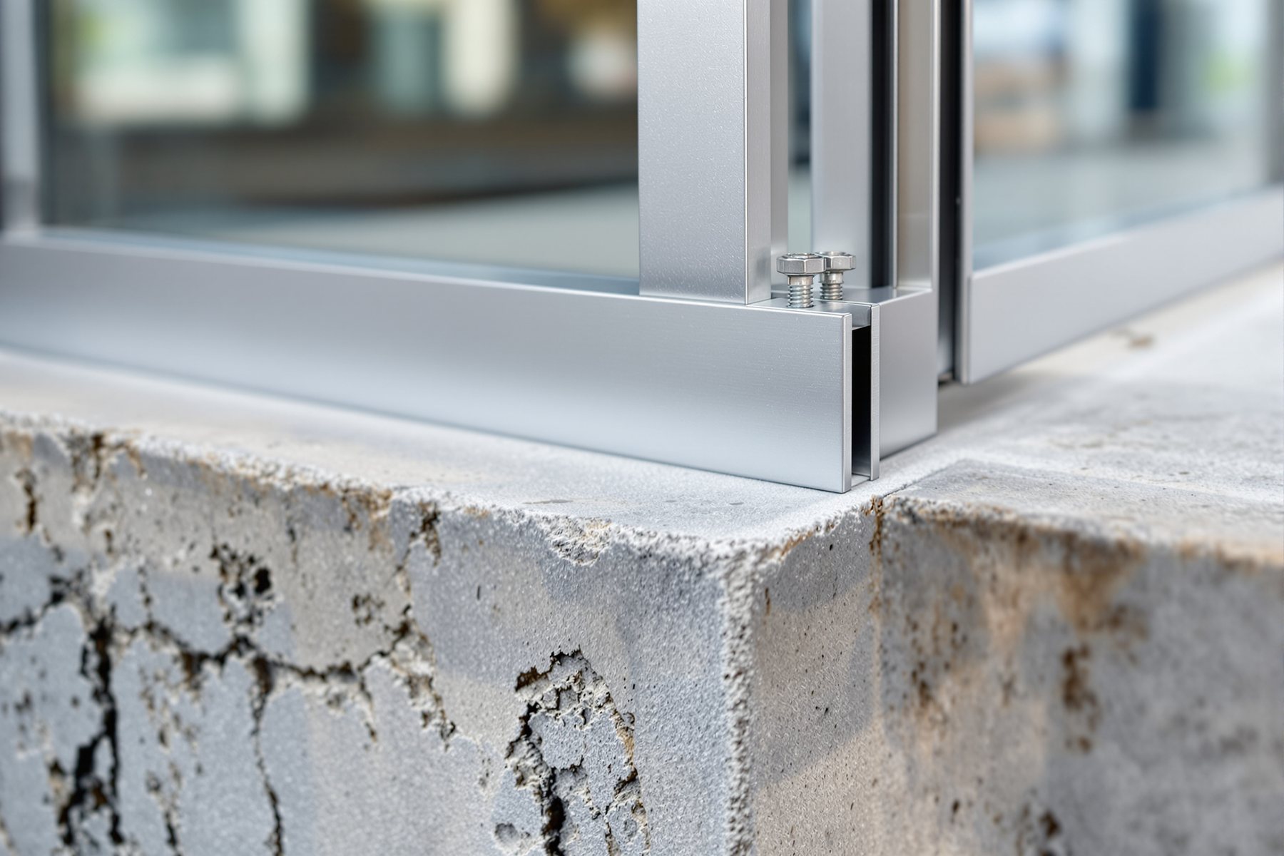
A tower's entire glass skin hangs from steel brackets you could hold in one hand - and every one of them reconciles a concrete frame built to plus or minus 25 mm with an aluminium skin built to plus or minus 2 mm.
Follow any load on a facade to its end and you arrive at the same small, unglamorous component: a steel **bracket** bolted to a slab. The dead weight of an entire storey of cladding, and the wind suction trying to tear panels off the building, all funnel through these fixings into the structure. They are the last link in the load path and the first place a facade fails catastrophically - a bracket that pulls out drops a panel onto the street. They are also the great **reconciler**: the concrete frame is cast to coarse tolerances (plus or minus 25 mm is normal), the aluminium skin is fabricated to a couple of millimetres, and the bracket - adjustable in three directions - is what lets the precise skin hang true off the rough frame. Get the brackets and anchors right and the whole engineered facade has somewhere to stand. Get them wrong and nothing else matters.
The load path to the slab - and the fixings that complete it
Skin to mullion to bracket to anchor to slab - the chain that must never break
Every facade has one continuous structural story: glass -> framing (mullion/transom) -> bracket -> anchor -> building structure. Wind pressure on the glass passes to the framing that holds its edges; the framing spans between brackets; the brackets transfer load into anchors; the anchors deliver it to the slab edge or column. Dead load (self-weight) runs down this same chain to the slab, while wind pushes and pulls horizontally through it.
Each bracket typically resolves loads in three directions: vertical (the dead weight it hangs, often at a 'dead-load' or 'pin' bracket), horizontal in-out (wind push and the critical wind suction pulling the panel off), and horizontal lateral (in-plane shear and seismic). On a unitised system the panels usually hang from a dead-load bracket at the top that carries gravity, with a wind-load (or restraint) bracket lower down that takes only the in/out wind and is left free to move vertically - separating the load functions so movement (Lesson 4.2) is not fought. The chain is only as strong as its weakest link: one undersized anchor and the whole panel is at risk.
Glass to mullion to bracket to anchor to slab. Wind sizes the link in tension; gravity sizes the link in shear; and the weakest link is the whole story.
Cast-in channels, post-installed anchors, and the three-way adjustable bracket
The bracket connects to the structure two ways. Cast-in channels and embeds (e.g. serrated channel or steel plate) are set into the formwork before the concrete is poured. They are the gold standard - high, predictable capacity, no drilling into reinforcement, and a serrated channel gives free vertical adjustment along its length. The catch is they must be located accurately at the pour, when the facade design may not be final.
Post-fixed (post-installed) anchors are drilled into cured concrete afterwards - expansion anchors or, better for tension, chemical/adhesive anchors. They are flexible (placed once the facade is set out) but depend entirely on installation quality, real concrete strength, edge distances and avoiding the rebar; their capacity is lower and more variable, and slab-edge anchors are vulnerable to the edge-distance reduction and to concrete cone/edge breakout failure.
The bracket between the fixing and the panel provides the magic of facades: three-way adjustability. Slotted holes and shims let the installer move the panel up/down, in/out and left/right to reconcile the rough frame with the precise skin and to set out a true, plumb line of glass. This adjustability is the tolerance system of the whole facade.
Design the anchor for the worst pull, keep the edge distance, and respect what cannot be adjusted on site
An anchor is checked against several failure modes, and the lowest governs: steel failure of the bolt (shear and tension), concrete cone/pull-out in tension, concrete edge breakout (the big risk near a slab edge), and pry-out in shear. Tension capacity falls sharply as you approach an edge - and facade anchors live at slab edges - so edge distance and embedment depth are not details to trim. The governing load is usually wind suction (tension on the out-pulling anchor) combined with the dead-load shear, checked against a combined tension-shear interaction.
Tolerance has limits. The bracket buys ~plus or minus 25-50 mm of adjustability in each direction - enough to reconcile a normal frame, but not enough to fix a slab cast 80 mm out of position. When the structure is built worse than the bracket's range, the facade installer is stuck: re-pack, re-drill, or wait for the frame to be corrected. This is why surveying the structure before fabrication matters, and why the facade engineer specifies a frame tolerance the brackets can absorb. Brackets are forgiving, but they are not infinitely forgiving - and the moment a panel is hung, the load path they form is carrying lives below.
Brackets are invisible to you, but they need room and a place to land. A razor-thin shadow gap at the slab edge, a cantilevered floor plate, or a column-free glazed corner can leave nowhere for a bracket to reach the structure - and the fix is an expensive special steel sub-frame. When you design a slab edge or a dramatic overhang, ask the facade engineer early where the cladding will be fixed and whether the structure can take cast-in channels. The most elegant facade still has to hang off something.
Own the whole load path and design every anchor to the governing failure mode - and remember that near a slab edge, concrete edge breakout, not steel, usually governs in tension, with wind suction as the worst case. Prefer cast-in channels for predictable capacity; if forced post-fixed, use adhesive anchors for tension, verify the real concrete strength, keep edge distances and embedment, and check the combined tension-shear interaction. Separate dead-load and wind-restraint brackets so the movement strategy from Lesson 4.2 is honoured, specify a structural-frame tolerance the bracket adjustability can absorb, and require the structure to be surveyed before fabrication.
Brackets are where the facade meets the building, and three things matter on site. **Adjustability**: use the slots and shims to set the panels to a true, plumb line - the bracket exists to reconcile the rough frame with the precise skin. **Edge distance and embedment**: a post-fixed anchor too close to the slab edge or not drilled deep enough is dangerously weak - drill to the spec, hit sound concrete, miss the rebar. **Do not improvise**: never substitute an anchor type, shorten an embedment or move a fixing closer to the edge to make life easier. Every bracket is carrying a panel above someone's head.
IS 456 / IS 875 (Parts 3 & 5)
Concrete & loads (India)
IS 456 governs the concrete the anchor is set into; IS 875-3/5 give the wind load and combinations the bracket must carry. India lacks a single dedicated concrete-anchor design standard, so EN 1992-4 or ACI 318-17 Ch.17 are widely used for the anchor calculation.
EN 1992-4 / ACI 318-17 Ch.17
Concrete anchor design
The global methods for cast-in and post-installed anchors - covering steel, concrete cone, pull-out, edge breakout and pry-out, and tension-shear interaction. Capacities depend on the manufacturer's tested data (ETA/ICC report), not just the formula.
ETAG 001 / AC308 (anchor approvals)
Post-installed anchor qualification
The approval routes (European Technical Assessment, ICC-ES) that give a specific anchor its design values in cracked or uncracked concrete. Use the anchor's own approval data; generic values can be unconservative, especially for tension near an edge.
CWCT / EN 13830
Curtain-wall fixing & tolerance
Set the curtain-wall performance and the movement/tolerance the fixings must accommodate. They define what the bracket must achieve, not the concrete-anchor capacity, which comes from the anchor code above.
“An anchor bolt's strength is just the strength of the steel bolt, so a strong bolt means a strong fixing.”
The bolt is often the _strongest_ part of the fixing. A facade anchor can fail by pulling a cone of concrete out, by breaking out the edge of the slab (the common failure at slab edges, where facade anchors live), or by pry-out in shear - all at loads below the steel's capacity. The governing capacity is the **lowest** of all failure modes, and near an edge it is usually a concrete failure, not the bolt. That is why embedment depth, edge distance and real concrete strength matter as much as the bolt grade - and why 'it's a big bolt, it'll be fine' is how panels come loose.
Worked example - check a curtain-wall bracket and its anchor
We have the panel loads from Lesson 4.1. Now follow them into a single dead-load bracket and verify the anchor that fixes it to the slab edge.
The panel loads (Lesson 4.1), the panel self-weight, the anchor's ETA/ICC capacity data for the actual concrete and edge distance, and the EN 1992-4 / ACI 318 interaction check.
GIVEN (one dead-load bracket carrying a unitised panel, fixed to slab edge):

  Panel size            1.5 m x 3.5 m = 5.25 m2
  Panel self-weight     w = 0.65 kN/m2  ->  Wp = 0.65 x 5.25 = 3.4 kN
  Brackets per panel    2  (each carries half the gravity)
  SLS wind suction      p = 2.0 kPa = 2.0 kN/m2  (1.0x, Lesson 4.1)
  ULS factors           1.5 x wind ,  1.5 x dead (for anchor design)
  Anchor: 2 x M12 adhesive anchors, 100 mm embed, near slab edge
  Anchor capacities (from the anchor's ETA, this concrete & edge distance):
     Tension  N_Rd = 9.0 kN/anchor   Shear V_Rd = 12.0 kN/anchor
Interaction check: (N_Ed/N_Rd) + (V_Ed/V_Rd) <= 1.0- 1Gravity per bracket (shear on the anchors). Each panel weighs Wp = 3.4 kN, shared by 2 dead-load brackets: 3.4 / 2 = 1.70 kN per bracket. Factored: V_Ed = 1.5 x 1.70 = 2.55 kN of vertical shear at the bracket.
- 2Wind suction on the panel (tension pulling the bracket off). Suction force = p x area = 2.0 kN/m2 x 5.25 m2 = 10.5 kN over the panel. Shared by the bracket group; take this bracket's tension share ~ half = 5.25 kN. Factored: N_Ed = 1.5 x 5.25 = 7.9 kN of tension.
- 3Distribute to the two anchors in the bracket. Tension per anchor = 7.9 / 2 = 3.95 kN; shear per anchor = 2.55 / 2 = 1.28 kN.
- 4Tension check. NEd = 3.95 kN per anchor vs NRd = 9.0 kN. Utilisation = 3.95 / 9.0 = 0.44 -> OK in tension alone.
- 5Shear check. VEd = 1.28 kN per anchor vs VRd = 12.0 kN. Utilisation = 1.28 / 12.0 = 0.11 -> OK in shear alone.
- 6Combined tension-shear interaction (the real check). (NEd/NRd) + (VEd/VRd) = 0.44 + 0.11 = 0.55 <= 1.0 -> the anchor group passes with ~45% reserve. The tension (wind suction) dominates, exactly as expected for a facade anchor.
- 7Respect the edge. The NRd of 9.0 kN already reflects the slab-edge breakout reduction from the anchor's ETA. Had the bracket been forced even closer to the edge, NRd would drop sharply and the same N_Ed could fail it - which is why edge distance, not bolt grade, is the number to defend on site.
You’ll walk away with
A verified fixing: a 2 x M12 adhesive-anchor dead-load bracket carrying 3.95 kN tension and 1.28 kN shear per anchor at a combined utilisation of 0.55 - safe, with the wind-suction tension governing and the slab-edge breakout capacity (not the bolt) being the value that matters. The complete load path from glass to slab, closed and checked.
Two quick fixing checks.
- 01Re-run the interaction if the bracket is pushed to a tight edge where N_Rd falls to 5.0 kN: utilisation = 3.95/5.0 + 1.28/12.0 = 0.79 + 0.11 = 0.90 - still under 1.0 but with little reserve, showing how fast edge distance erodes safety.
- 02Trace the full load path of one corner panel from Lesson 4.1 (14.2 kN suction) through glass, mullion, two brackets and four anchors, and note where the number gets divided - the load path is a chain of sharing, and the last link (the anchor at the edge) is the one to watch.
Every facade load travels glass -> framing -> bracket -> anchor -> slab, and the brackets both complete that chain and reconcile a rough frame with a precise skin through three-way adjustability. Cast-in channels beat post-fixed anchors for predictable capacity; near a slab edge an anchor is governed by concrete edge breakout in tension (worst case: wind suction), not the bolt, checked by a combined tension-shear interaction. The weakest link in the chain is the whole facade.
Load path: glass -> mullion/transom -> bracket -> anchor -> slab, in three directions (vertical dead, in-out wind incl. suction, lateral/seismic). Separate dead-load and wind-restraint brackets to allow movement. Cast-in channels (predictable, adjustable) vs post-fixed anchors (flexible, install-dependent, lower/variable). Anchor governed by the lowest of steel/cone/edge-breakout/pry-out - usually edge breakout in tension at a slab edge. Check combined tension-shear <= 1.0. Brackets give ~+/-25-50 mm adjustability - survey the frame first.
What is the load path of a facade from the skin to the structure?
Wind and dead loads travel glass -> framing (mullion and transom) -> bracket -> anchor -> building structure (slab edge or column). Wind pressure on the glass passes to the framing that supports its edges, the framing spans between brackets, the brackets transfer load into anchors, and the anchors deliver it to the slab. Each bracket resolves load in three directions - vertical dead weight, horizontal wind push and suction, and lateral/seismic shear - and the chain is only as strong as its weakest link, which is usually the anchor at the slab edge.
What is the difference between cast-in channels and post-fixed anchors?
Cast-in channels and embeds are set into the formwork before the concrete is poured, giving high, predictable capacity, built-in vertical adjustment along the channel, and no drilling into reinforcement - but they must be positioned accurately at the pour. Post-fixed (post-installed) anchors are drilled into cured concrete afterwards, so they are flexible to set out once the facade is fixed, but their capacity is lower and more variable, depends heavily on installation quality, real concrete strength and edge distance, and is vulnerable to concrete edge breakout near a slab edge. Cast-in is preferred where the design is settled early; post-fixed where flexibility is needed.
Why does edge distance matter so much for a facade anchor?
Facade anchors usually sit near the slab edge, and a concrete anchor in tension can fail by breaking out a cone or wedge of concrete toward the free edge well before the steel bolt itself yields. As the anchor gets closer to the edge, this concrete edge-breakout capacity drops sharply, and since wind suction puts the anchor in tension, edge breakout is often the governing failure mode. So embedment depth and edge distance - not the bolt grade - usually decide the fixing's real capacity, which is why they must be installed exactly to specification and never trimmed on site.
Peer-reviewed journals & authoritative standards
- 01Bedon, C. et al. Performance of structural glass facades under extreme loads - design methods, existing research, current issues and trends. Construction and Building Materials, 163. — Construction and Building Materials (Elsevier), 2018.
- 02Wind Resistance Performance Evaluation of a Cable-Type Curtain Wall System on Reinforced Concrete High-Rise Buildings. — (peer-reviewed; University of Bath research portal), 2021.
- 03Material Selection and Characterization for a Novel Frame-Integrated Curtain Wall. — Materials / NCBI-PMC, 2021.
_That closes the structural module - load, movement, glass and the fixings that carry it all to the building. The skin now stands up and stays attached. Next we make it keep the weather out: Module 5 turns to weatherproofing, air and water, and how facades actually leak._