
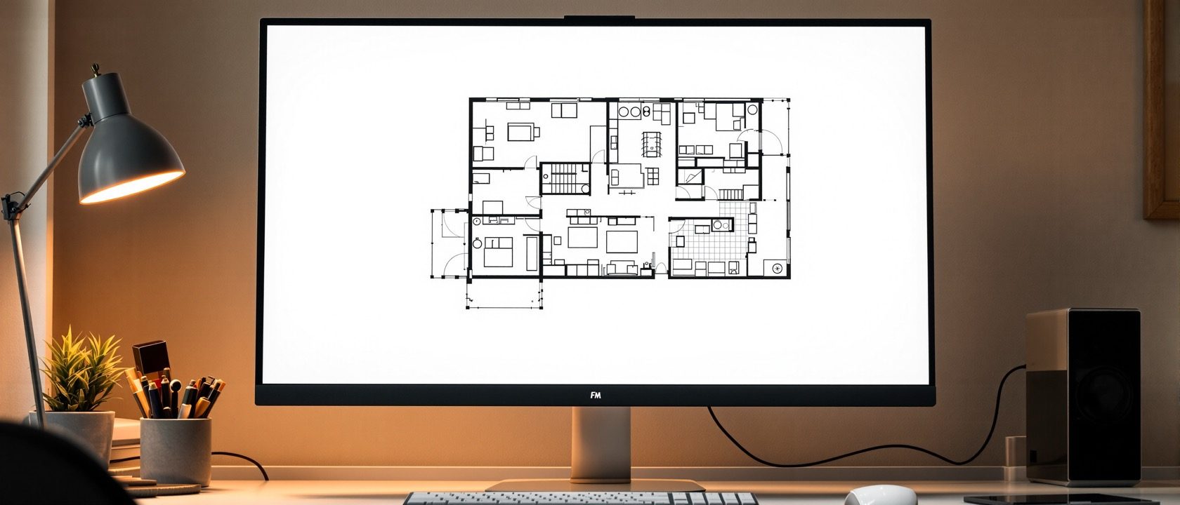
From Board to CAD
Why digital, how CAD thinks, and the golden rule of scale.
CAD does not throw away the drawing-board skills of the earlier graphics courses — it presupposes them. A line in CAD is not a mark but a mathematical object with exact coordinates, so the drawing becomes data you can edit, copy, layer and share. Learn what CAD is and is not, why vector beats raster for a designer, the three ways to place a point, and the golden rule of the whole course: draw at full size, scale only at output.
Learning objectives
By the end of this lesson, you will be able to — mapped to the course outcomes for Computer Studio I:
Explain what CAD is and is not, and its honest advantages and limits.
Distinguish vector from raster and say why it matters for a designer.
Specify points by absolute, relative and polar coordinates.
Explain drawing at 1:1 full size, units, and the WCS/UCS.
The shift, and how CAD thinks
Why CAD presupposes drawing-board discipline, its honest limits, and the foundational vector-versus-raster distinction.[1, 4]
A drawing board, not a designer
CAD does not replace drawing-board knowledge — it PRESUPPOSES it; line weights, scale, dimensioning and poché still govern a good CAD drawing. What CAD IS: a system for building drawings from geometry defined by COORDINATES and NUMBERS, so a line is not a mark but a mathematical object that can be edited, copied, measured, layered and shared. What it is NOT: automatic design, or a guarantee of correctness. Two honest limits — GARBAGE IN, GARBAGE OUT (a wall drawn 10 mm short is exactly 10 mm short forever), and OVER-RELIANCE (the ease of nudging tempts you to eyeball). The board's discipline matters MORE in CAD, not less.[1, 4]
Coordinates, full-size drawing & units
The Cartesian coordinate system, the golden rule of drawing at 1:1 and scaling only at output, and units, the WCS/UCS and the command line.[1, 2, 3]
The golden rule
The most important idea in the course: DRAW EVERYTHING AT 1:1, real-world size, in MODEL SPACE — a 3-metre wall is drawn 3000 units long, never '30 mm at 1:50'. You never scale the geometry. Scale is applied ONLY when you place the drawing on a sheet to plot (paper space, Unit V). This inverts the board habit of scaling as you draw — and it means every dimension is always true, and the same model plots at 1:50, 1:20 or 1:5 without redrawing.[1]
Try it — the coordinate-entry explorer
Pick absolute, relative or polar entry to see the syntax and exactly where the point lands.
Coordinate-entry explorer · three ways to place a point
Absolute coordinates
syntax: X,Y · e.g. 3000,0
Measured from the fixed origin (0,0). Exact, but you must know the point's true position — used mostly for the first point.
The @ means “relative to the last point”; < means “at angle”. Draw everything at 1:1 full size.
At a glance
| Aspect | One side | The other |
|---|---|---|
| CAD's role | Myth: it designs for you | Reality: a faster, accurate, editable drawing board |
| Accuracy | Myth: CAD is accurate automatically | Reality: precise to your input — it reproduces errors too |
| Drawing scale | Myth: draw at 1:50 like the board | Reality: draw 1:1; scale only at output |
| Vector vs raster | DWG: editable vector geometry | JPG: flat pixels, not rescalable losslessly |
| Absolute vs relative | X,Y from the fixed origin | @X,Y from the last point |
Key terms
Geometry as math (scales losslessly, editable) versus a pixel grid (blurs when enlarged).
Point entry from the origin (X,Y), from the last point (@X,Y), or by distance & angle (@d<a).
The infinite full-size world where you draw everything at 1:1.
Geometry is always real size; scale is applied only at plotting — never to the geometry.
The fixed world coordinate frame versus a temporary user-defined origin/orientation.
CAD's text dialogue — it always prompts the next input; read it.
Practice task
On paper (or in any CAD you have access to), plan the coordinate sequence to draw a 3600 × 4200 mm room as a closed rectangle starting at the origin, writing the exact entry for each corner using relative coordinates (@X,Y) — then redo the first wall using polar entry (@d<a). Explain in two sentences why you draw it at true size (3600, not 72 “at 1:50”) and what breaks if you mix millimetres and metres in one file.
Self-assessment
1. In CAD you should draw an interior —
2. The key difference between a DWG and a JPG of the same plan is that the DWG is —
3. Typing @3000,0 places a point —
Recap
References & further reading
- [1]Autodesk, AutoCAD Help / User's Guide — 'About Coordinate Entry', 'Specify Units and Unit Formats', 'The User Interface' (help.autodesk.com).
- [2]George Omura & Brian C. Benton, Mastering AutoCAD and AutoCAD LT, Sybex/Wiley (interface, coordinate systems, drawing setup).
- [3]Ellen Finkelstein, AutoCAD and AutoCAD LT Bible, Wiley (Cartesian, relative and polar coordinates; units).
- [4]Beverly L. & James M. Kirkpatrick, AutoCAD for Interior Design and Space Planning, Pearson (fundamentals for interior students).
Further reading
- George Omura & Brian C. Benton — Mastering AutoCAD and AutoCAD LT.
- Ellen Finkelstein — AutoCAD and AutoCAD LT Bible.
- Kirkpatrick — AutoCAD for Interior Design and Space Planning.
Sources gathered and fact-checked June 2026. Published values vary by source, sample and method — treat as indicative and confirm against the cited standard before structural use.
The author
Amogh N P
Architect, interior designer, and creative polymath. Studio Matrx began in his notebooks — his vision of design made honest, useful, and open to everyone. Its Academy is written and taught in his memory, and free, forever.
More about Amogh →