

Working & Electrical Drawings
The drawings that actually build the building — and power it.
This is the project unit, and the point of the whole course. A working drawing set is the instructions a contractor builds from — and an architect must also understand the services that make a building work, beginning with the electrical layout. Here a drawing stops being a picture and becomes a legal, costed instrument.
Learning objectives
By the end of this lesson you will be able to — mapped to the course outcomes for Architectural Graphics & Computer Studio:
Distinguish working (construction) drawings from design and presentation drawings.
List the contents of a working set — plans, sections, details, schedules, specifications.
Read and lay out an electrical drawing with standard IS symbols, points and circuits.
Describe the Indian sanction / submission set and why precision has legal weight.
Instructions to build
Working (construction) drawings leave nothing to guesswork — every size, level, material and junction is stated, across a coordinated set of sheets. Select a topic.[1]
Instructions to build
Working (construction or production) drawings are the drawings a contractor actually builds from — fully dimensioned, specified and coordinated — as distinct from the design and presentation drawings that sell the idea. Their job is to leave nothing to guesswork: every size, level, material and junction is stated.[1]
| Aspect | Design / presentation drawing | Working drawing |
|---|---|---|
| Purpose | Explore & sell the idea | Instruct construction |
| Audience | Client, jury, public | Contractor, engineer, authority |
| Content | Concept, mood, 3-D views | Dimensions, specs, details, schedules |
| Tolerance for ambiguity | Some — it is suggestive | None — it must be exact |
Schedules & specifications
Repetitive elements are tabulated, not redrawn — a door/window schedule lists each type against a tag on the plan, and in CAD those tags are block attributes that can be extracted automatically. Written specifications fix the quality the drawings cannot show.[1]
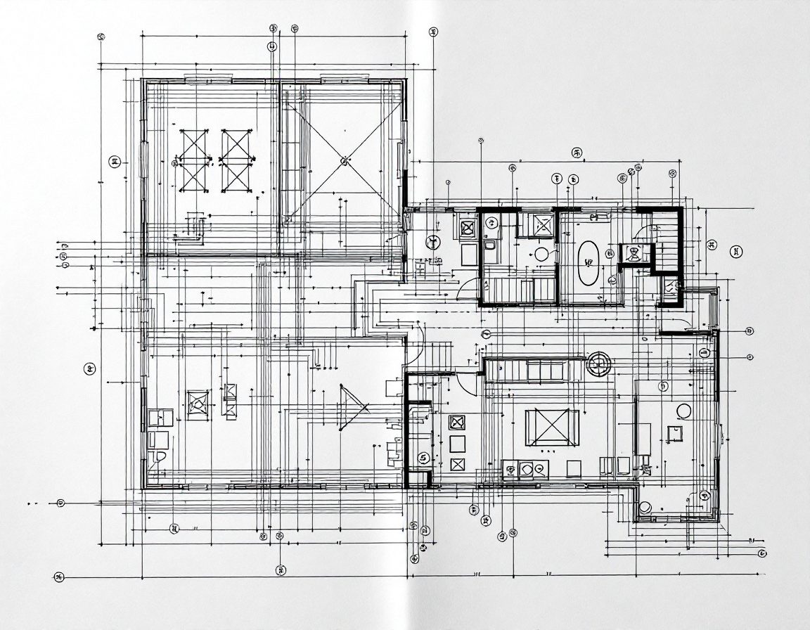
The electrical layout
The electrical layout overlays the plan with points and circuits — lights, fans, switches, sockets and the distribution board. India's symbols come from IS 12032 (Part 11); the installation follows IS 732 and the National Building Code 2016, Part 8.[2, 3, 4]
| Symbol | What it marks |
|---|---|
| Lighting point | A ceiling or wall light outlet |
| Ceiling fan point | Fan outlet with a regulator |
| One-way / two-way switch | Two-way pairs control one light from two places (e.g. a stair) |
| Socket outlet (5 A / 15 A) | 5 A for small appliances; 15 A for heavy loads |
| Distribution board (DB) | Splits the supply into protected circuits |
Drawings with legal weight
For building approval in India a defined submission set — site plan with setbacks, floor plans, sections, elevations, services and an area/FAR statement — must comply with the NBC and the local Development Control Regulations. Here precision has consequences.[5, 6]
Self-assessment
1. Working (construction) drawings differ from presentation drawings because they:
2. On an Indian electrical layout, the standard set of graphical symbols comes from:
3. A door/window schedule is used so that:
Recap
References & further reading
- [1]The architect's construction-drawing guide — working set sheet types, schedules and specs. CW Architecture. https://www.cwarch.design/the-architects-construction-drawing-guide
- [2]IS 12032 (Part 11):1987 — Graphical symbols for architectural and topographical electrical installation plans (≡ IEC 60617-11). BIS. https://archive.org/details/gov.in.is.12032.11.1987
- [3]IS 732:2019 — Code of practice for electrical wiring installations (fourth revision). BIS. https://archive.org/details/gov.in.is.732.2019
- [4]National Building Code of India 2016, Part 8 ‘Building Services’, Section 2 ‘Electrical and Allied Installations’. BIS. https://infralens.in/code/NBC-2016-Part-8-2016
- [5]Model Building Bye-Laws — building plan approval and the required submission drawings. MoHUA, Government of India. https://mohua.gov.in/upload/uploadfiles/files/Chap-2.pdf
- [6]Architectural drawing — working drawings and the construction documentation set. Overview. https://en.wikipedia.org/wiki/Architectural_drawing
Further reading
- Ching, F.D.K. (2014). Building Construction Illustrated (5th ed.). Hoboken, NJ: Wiley — what working drawings and details describe.
- Onstott, S. (2014). AutoCAD 2015 and AutoCAD LT 2015 Essentials. Indianapolis: Autodesk Official Press — producing a coordinated set.
- Fiorello, J.A. (2011). CAD for Interiors: Beyond the Basics. Hoboken, NJ: Wiley — services, schedules and documentation.
Sources gathered and fact-checked June 2026. Published values vary by source, sample and method — treat as indicative and confirm against the cited standard before structural use.
The author
Amogh N P
Architect, interior designer, and creative polymath. Studio Matrx began in his notebooks — his vision of design made honest, useful, and open to everyone. Its Academy is written and taught in his memory, and free, forever.
More about Amogh →