

Mini Project — A Coordinated Set
Plan, elevation, section and details that describe one building together.
Now the tools serve a building. The mini-project draws a small house as a coordinated set — plan, elevation, section and details — where every view agrees with the others. This is where the symbols, layers and conventions of the earlier units come together into one consistent drawing.
Learning objectives
By the end of this lesson you will be able to — mapped to the course outcomes for Architectural Graphics & Computer Studio:
Explain how plan, elevation, section and detail describe one building together.
Coordinate the views — section cut on plan, shared levels, aligned grids.
Use the conventions of cut vs seen, poché and detail callouts correctly.
Organise the set with a consistent layer scheme and reusable blocks.
Four views, one building
No single view describes a building; together, the plan, elevations, section and details fix it unambiguously — and a plan, remember, is itself a horizontal section. Select a topic.[1]
Four views, one building
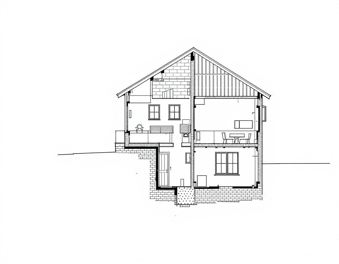
A small building is described by a family of orthographic views: the PLAN (a horizontal cut, looking down), the ELEVATIONS (the faces, seen straight on), the SECTION (a vertical cut, revealing heights and structure) and DETAILS (close-ups of how parts meet). No single view is enough — together they fix the building unambiguously.[1]
| View | What it is | What it shows |
|---|---|---|
| Plan | Horizontal section ~1.2 m above floor, looking down | Room layout, walls, openings, circulation |
| Elevation | A face seen straight on (orthographic) | Proportion, openings, materials, heights |
| Section | Vertical cut through the building | Floor-to-floor heights, structure, roof |
| Detail | A close-up at large scale (1:5, 1:1) | How parts actually meet and are built |
Cut versus seen
The single most important convention: what the section cuts through is drawn heaviest (and filled with poché); what is merely seen beyond the cut is lighter; what is hidden or above is dashed. In CAD this hierarchy is controlled by layer.[3, 1]
Order from the start
Set the layers before you draw — walls, columns, openings, furniture, dimensions, text, hatch and grid, each its own colour and lineweight — and draw repeated elements as blocks. A disciplined scheme lets one model plot as a clean plan, a furniture plan or a structural grid.[4]
Self-assessment
1. A floor plan is best described as:
2. On a plan, the heaviest lineweight is given to:
3. The section line drawn on a plan tells you:
Recap
References & further reading
- [1]Architectural drawing — the set; floor plan as a horizontal section; sections and elevations. Overview. https://en.wikipedia.org/wiki/Architectural_drawing
- [2]The architect's construction-drawing guide — sheet types, coordination and how views relate. CW Architecture. https://www.cwarch.design/the-architects-construction-drawing-guide
- [3]IS 962:1989 — conventions for cut/seen, poché and detailing on building drawings. BIS. https://law.resource.org/pub/in/bis/S03/is.962.1989.pdf
- [4]Architectural graphics 101 — line hierarchy, symbols and reading conventions. Life of an Architect. https://www.lifeofanarchitect.com/architectural-graphics-101-symbols/
Further reading
- Ching, F.D.K. (2023). Architectural Graphics (7th ed.). Hoboken, NJ: Wiley — plan, section, elevation and their conventions.
- Ching, F.D.K. (2014). Building Construction Illustrated (5th ed.). Hoboken, NJ: Wiley — what the details actually describe.
- Onstott, S. (2014). AutoCAD 2015 Essentials. Indianapolis: Autodesk Official Press — organising a set on layers and blocks.
Sources gathered and fact-checked June 2026. Published values vary by source, sample and method — treat as indicative and confirm against the cited standard before structural use.
The author
Amogh N P
Architect, interior designer, and creative polymath. Studio Matrx began in his notebooks — his vision of design made honest, useful, and open to everyone. Its Academy is written and taught in his memory, and free, forever.
More about Amogh →