

Drafting for Architectural Design
The CAD toolset — geometry, editing, precision, layers, blocks and hatches.
This is the working core of CAD — the tools you will use every day. Build geometry with a handful of creating tools, reshape it (mostly) with the editing tools, and place every point exactly by typing coordinates rather than guessing. Then the three ideas that separate a tidy professional drawing from a tangle: layers, blocks and associative hatches.
Learning objectives
By the end of this lesson you will be able to — mapped to the course outcomes for Architectural Graphics & Computer Studio:
Build geometry with the creating tools and reshape it with the editing tools.
Place points exactly using absolute, relative and polar coordinates, ortho and osnap.
Organise a drawing on layers and control properties ByLayer.
Reuse symbols as blocks with attributes and fill regions with associative hatches.
Create, then edit
A few primitives draw almost everything, and most of your time is spent editing them — offsetting a line into a wall, trimming junctions, mirroring and arraying. Select a topic.[1]
The creating tools
A handful of primitives draw almost everything: LINE and the POLYLINE (a connected, single-object chain), CIRCLE and ARC, RECTANGLE and POLYGON, plus ELLIPSE and SPLINE for curves. The polyline matters — a wall or boundary drawn as one polyline can be offset, filleted and hatched as a unit.[1]
Precision — never eyeball it
Geometry must be exact, so you state position rather than guess it — absolute, relative and polar coordinates, with ortho and object snap to keep everything clean.[2]
| Mode | You type | It means |
|---|---|---|
| Absolute | 120,90 | Go to the point X=120, Y=90 measured from the drawing origin (0,0). |
| Relative | @3000,0 | From the last point, step 3000 to the right and 0 up — a 3 m wall. |
| Polar | @5000<30 | From the last point, go 5000 units at 30° — a length and a direction. |
Layers — the soul of CAD
Layers sort the drawing into controllable overlays — walls, doors, dimensions, furniture, grid — each with its own colour and lineweight. Set properties ByLayer and one change updates everything on the layer; standards like ISO 13567 and the US National CAD Standard give layers consistent names.[3, 4, 5]
Try it — layers on, layers off
The same drawing, controlled by its layers. Toggle each and watch what appears and disappears — exactly how a plan, a furniture plan or a structural grid all come from one model.
Blocks & hatches
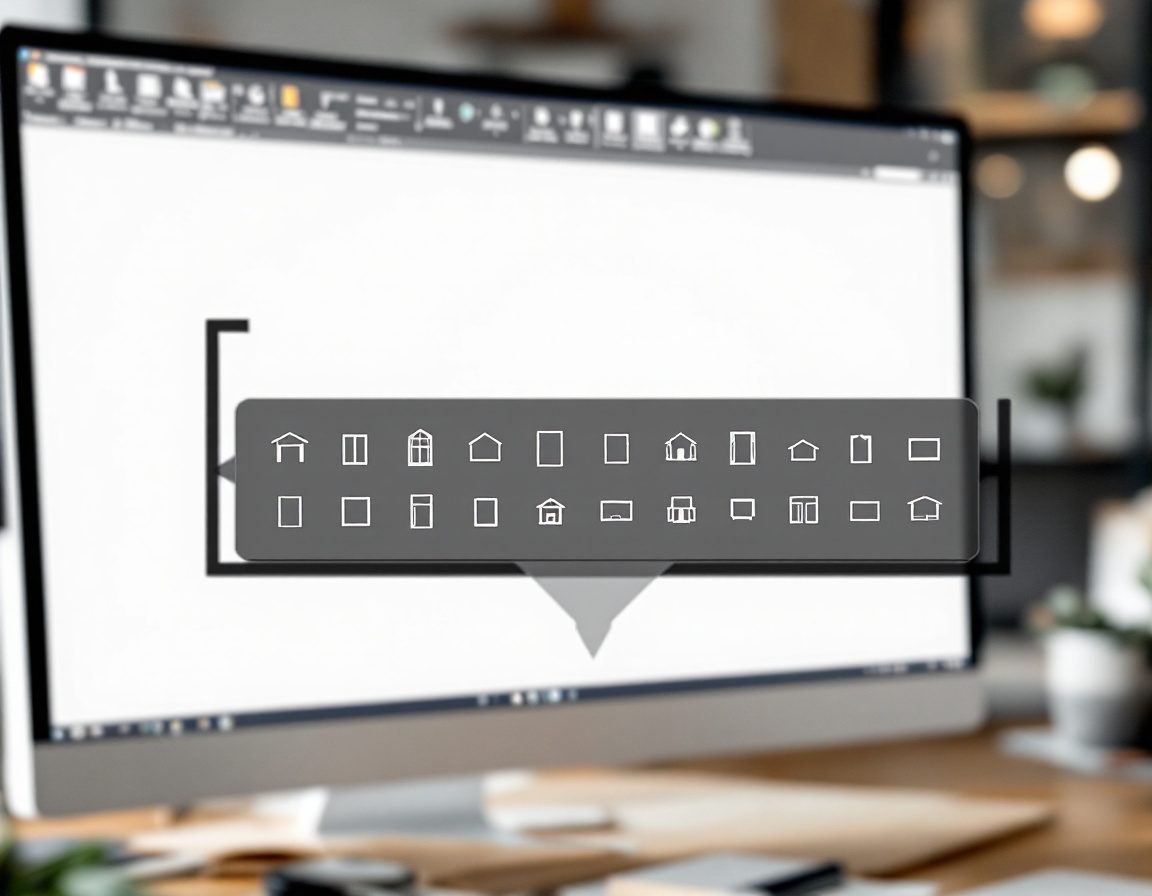
Draw a door, a WC or a column once as a block — reuse it everywhere, redefine it once, and extract its attributes into a schedule. Fill a region with an associative hatch that re-flows when its boundary changes.[3, 6]

Self-assessment
1. To draw a wall exactly 3000 mm to the right of your last point, you type:
2. Setting an object's colour, linetype and lineweight to ‘ByLayer’ means:
3. An associative hatch is useful because:
Recap
References & further reading
- [1]AutoCAD creating & editing tools — line, polyline, offset, trim, fillet, array (concepts, vendor-neutral). Autodesk Help. https://help.autodesk.com/view/ACD/2024/ENU/
- [2]Precision / coordinate entry — absolute, relative, polar; ortho; object snap; grid & snap. Autodesk Help. https://help.autodesk.com/view/ACD/2024/ENU/?guid=GUID-85D8C41C-9C3E-440F-BD60-61848DD27219
- [3]Layers, blocks and associative hatches — organisation and property control (ByLayer). Autodesk Help. https://help.autodesk.com/view/ACD/2024/ENU/?guid=GUID-6294A87E-3AB5-40B2-95D9-DBC34E494932
- [4]ISO 13567-1:2017 — Technical product documentation: organization and naming of layers for CAD. ISO. https://www.iso.org/standard/70181.html
- [5]United States National CAD Standard (NCS) — incorporates the AIA CAD Layer Guidelines (e.g. A-WALL). NIBS. https://www.nationalcadstandard.org/
- [6]IS 962:1989 — material indications / hatching conventions for building drawings. BIS. https://law.resource.org/pub/in/bis/S03/is.962.1989.pdf
Further reading
- Onstott, S. (2014). AutoCAD 2015 and AutoCAD LT 2015 Essentials. Indianapolis: Autodesk Official Press — tools, precision, layers, blocks.
- Fiorello, J.A. (2011). CAD for Interiors: Beyond the Basics. Hoboken, NJ: Wiley — blocks, layers and drawing management in practice.
- Aouad, G. et al. (2012). Computer Aided Design Guide for Architecture, Engineering and Construction. London: Spon Press.
Sources gathered and fact-checked June 2026. Published values vary by source, sample and method — treat as indicative and confirm against the cited standard before structural use.
The author
Amogh N P
Architect, interior designer, and creative polymath. Studio Matrx began in his notebooks — his vision of design made honest, useful, and open to everyone. Its Academy is written and taught in his memory, and free, forever.
More about Amogh →