

Drafting Basics
From the board to the screen — and the language of symbols.
Drawing has moved to the screen — but the discipline has not changed. Digital drafting is the same precise, conventional drawing you learned on the board, only the geometry now lives in the computer as editable objects you can move, copy and measure. This first lesson sets up what CAD really is, the one habit that underlies everything, and the graphic language your drawings speak.
Learning objectives
By the end of this lesson you will be able to — mapped to the course outcomes for Architectural Graphics & Computer Studio:
Explain what CAD is — and correct the common myths about it.
Distinguish vector (object) drawing from raster (pixel) images.
Adopt the core habit — draw geometry at full size (1:1) in model space.
Represent doors, windows, materials and glass with standard symbols and hatches.
From the board to the screen
CAD is a category of tools, not a single program, and it drafts and documents — it does not design for you. It is the digital companion to the by-hand Architectural Graphics I conventions. Select a topic.[1, 2, 7]
Computer-aided drafting & design
CAD is using a computer to create, modify and document drawings — geometry stored as precise, editable objects rather than ink on paper. It is a category, not a single program: 2-D drafting (AutoCAD, DraftSight, the open-source LibreCAD/QCAD) and the BIM/3-D modellers (Revit, ARCHICAD, Vectorworks) are all CAD. The tool drafts and documents; it does not design for you.[1, 7]
Vector, not pixels — and full size
A CAD drawing is made of vector objects defined by coordinates and equations, not a grid of pixels — so it stays sharp at any zoom and every line can be edited. And you always draw at full real-world size (1:1) in model space; scale comes only at the plot.[3, 5]
| Aspect | Vector — a CAD drawing | Raster — a photo or scan |
|---|---|---|
| Made of | Objects — lines, arcs, polylines (coordinates + equations) | Pixels — a fixed grid of coloured dots |
| On zoom | Stays sharp at any magnification | Blurs / pixelates when enlarged |
| Editable | Each entity moved, trimmed, measured | Only the pixels; no separate objects |
| Typical use | Drafting — plans, sections, details | Photographs, scans, site images |
| Files | DWG (native), DXF (interchange) | JPEG, PNG, TIFF |
The graphic language
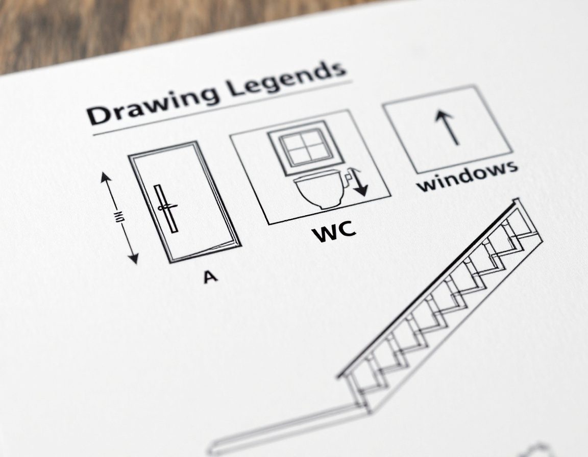
Plans are read by convention. Doors carry a swing arc, windows a wall break, stairs an up-arrow; sections, levels and north points orient the reader; and material hatches name what is cut. IS 962 standardises these for India.[6, 4]

Self-assessment
1. In CAD, you should draw a 4-metre wall as:
2. The key difference between a vector drawing and a raster image is:
3. ‘CAD = AutoCAD’ is:
Recap
References & further reading
- [1]Best 2D and 3D CAD drafting software — the CAD landscape (AutoCAD, DraftSight, LibreCAD, Revit, ARCHICAD). First In Architecture. https://www.firstinarchitecture.co.uk/best-2d-and-3d-cad-drafting-software/
- [2]AutoCAD — origin and history (Autodesk founded 1982; AutoCAD 1.0 shipped December 1982). Wikipedia. https://en.wikipedia.org/wiki/AutoCAD
- [3]Raster (bitmap) vs vector graphics — objects vs pixels, resolution independence. Overview. https://en.wikipedia.org/wiki/Vector_graphics
- [4]Architectural graphics 101 — standard symbols (doors, windows, sections, north point). Life of an Architect. https://www.lifeofanarchitect.com/architectural-graphics-101-symbols/
- [5]Drawing scale explained — draw at 1:1 in model space, scale at plot. AutoCAD Tips. https://autocadtips.com/blog/drawing-scale-explained-model-at-1-1-vs-plot-scale/
- [6]IS 962:1989 — Code of practice for architectural and building drawings (symbols & conventional representation of materials). BIS. https://law.resource.org/pub/in/bis/S03/is.962.1989.pdf
- [7]Sketchpad — Ivan Sutherland's pioneering interactive-graphics system (MIT, 1963). Britannica. https://www.britannica.com/technology/Sketchpad
Further reading
- Ching, F.D.K. (2023). Architectural Graphics (7th ed.). Hoboken, NJ: Wiley. ISBN 978-1-394-20626-1 — the graphic conventions and symbols.
- Onstott, S. (2014). AutoCAD 2015 and AutoCAD LT 2015 Essentials. Indianapolis: Autodesk Official Press (Sybex/Wiley).
- Uddin, M.S. (1999). Digital Architecture. New York: McGraw-Hill — drawing in the digital medium.
Sources gathered and fact-checked June 2026. Published values vary by source, sample and method — treat as indicative and confirm against the cited standard before structural use.
The author
Amogh N P
Architect, interior designer, and creative polymath. Studio Matrx began in his notebooks — his vision of design made honest, useful, and open to everyone. Its Academy is written and taught in his memory, and free, forever.
More about Amogh →