
 Lesson 2.1
Lesson 2.1 · The nD Dimensions
3D: The Coordinated Model
The base dimension is not a picture — it is space, resolved
A 3D render is not the 3D dimension of BIM. Space is.
Ask most people what '3D BIM' means and they will describe a walkthrough — a glossy fly-through of the finished building. That is a *picture*, and it is the least of what the 3D dimension does.
The real 3D dimension is spatial coordination: putting the architect's model, the structural engineer's model and the services engineer's model into one shared space, at true coordinates, so that the moment a duct wants to run through a beam, or a beam drops below a ceiling, or a pipe collides with a door, the conflict shows up — on screen, in the office, weeks before anyone pours concrete. 3D is not how the building *looks*. It is where every part of it actually *is*.
Everyone wants the fly-through. The value was in the collision nobody sees.
Two kinds of 3D — and only one is BIM's dimension
There is 3D that is a *representation* and 3D that is a *coordination*. A SketchUp massing, a rendered visual, a 3D CAD shell — these are the first kind: three-dimensional pictures. They look like the building but carry no reliable spatial data and cannot tell you whether two things fight for the same cubic metre.
The 3D dimension of BIM is the second kind. Every object sits at a real, shared coordinate; every discipline models in the same space; and the geometry is *trustworthy enough to test*. That is the difference between a model you look at and a model you can *interrogate* — and it is why the number '3D' in the nD sequence does not mean 'we made it three-dimensional', it means 'we resolved the building in space so its parts can be checked against each other'.
The federated model: many models, one coordinated space
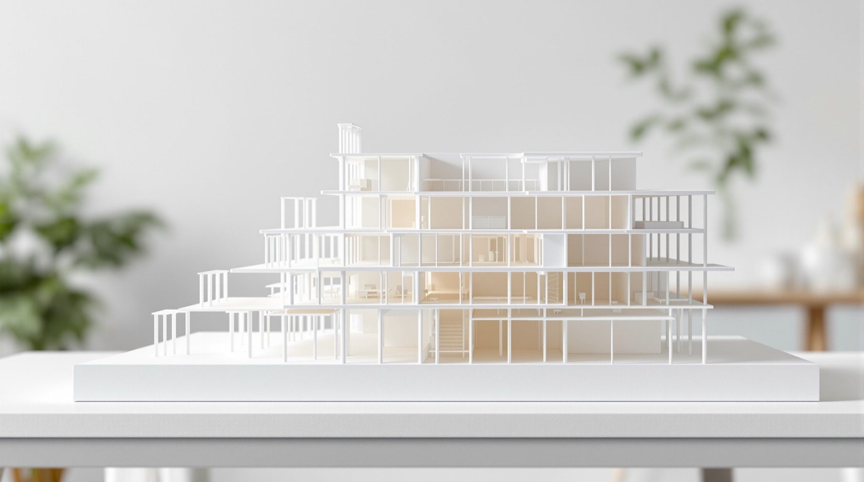
In a real project the architect, the structural engineer and the MEP (mechanical, electrical, plumbing) engineer each build their own model. Rather than merge them into one giant file, they are combined into a federated model — laid over one another at shared coordinates, kept separate but seen together. Each team owns and updates its own model; the federation is the coordinated whole they check against.
Inside that federation, clash detection does what no drawing set ever could: it automatically finds where two disciplines occupy the same space. A hard clash is a duct passing through a beam. A soft clash is a pipe too close to a wall to be insulated or maintained. Catch these on screen and you resolve them with a mouse; miss them and you resolve them on site with a cutting disc, a delay and an argument about who pays. (Module 6 covers clash detection and its limits properly — including why a clean clash report is never proof of a good building.)
3D is not the building made pretty. It is the building made checkable.
Why the base dimension carries the whole stack
Every dimension above 3D — time, cost, and everything after — hangs off the coordinated model. You cannot simulate a build sequence (4D) if the parts are not correctly placed in space. You cannot pull reliable quantities for cost (5D) if the geometry is wrong. The trustworthiness of every later 'D' is capped by the trustworthiness of the 3D beneath it.
That is why the base dimension is not the boring one — it is the load-bearing one. A well-coordinated 3D model with clean, correctly placed, correctly classified objects is the foundation the rest of BIM stands on. Get 3D wrong and the higher dimensions inherit the error and multiply it: a wrongly-modelled slab clashes in space, mis-sequences in time, and mis-prices in cost, all at once.
Three altitudes on the same idea
Read the band that fits you — or all three.
Learn it as space, not pictures. 3D BIM does not mean 'we drew it in three dimensions for looks'. It means every part of the building sits at a real, shared coordinate, so the model can be tested for conflicts. Picture the architecture, structure and services models stacked in the same space (a 'federated model'); clash detection then finds where a duct and a beam want the same spot. That spatial coordination — not the render — is the 3D dimension.
Model to be coordinated, not just to be seen. Your 3D work is only doing its job if it federates cleanly with the other disciplines: shared coordinates and levels, correct object classification, geometry that is accurate where it matters (and no more — see LOD in Module 3). The deliverable of good 3D is not a pretty view; it is a model that survives clash detection and gives the 4D and 5D teams something they can trust. Sloppy placement here becomes everyone's problem downstream.
Set coordination as a requirement, not a hope. Spatial coordination only happens if you mandate it: a shared coordinate system and level naming agreed up front, a clash-detection routine with owners and a cadence, and a federation strategy in the BEP (who publishes what, how often, into which CDE). The value case for 3D is rework avoided — clashes resolved on screen cost a fraction of clashes resolved on site. But it is a governed process: without agreed coordinates and a clash workflow, three good models still will not coordinate.
“We have a detailed 3D model, so our 3D BIM is done.”
Do it yourself
You can feel spatial coordination with three sheets of tracing paper — no software needed.
- 1On three transparent sheets, sketch the same simple room to the same scale: sheet A the architecture (walls, a door, a dropped ceiling at 2.7 m), sheet B the structure (a beam at 2.6 m), sheet C the services (a 300 mm duct running along the ceiling).
- 2Look at each sheet alone. Every one is fine on its own — no problem is visible.
- 3Now stack all three and hold them to the light. The beam at 2.6 m and the duct in the 2.7 m ceiling zone are fighting for the same space, and the beam pokes below the ceiling line. That overlap is a clash — and you only saw it once the models were *federated*.
- 4That stack-and-check is exactly what 3D BIM does, in space, automatically, across thousands of elements. Write one line: which clash would you rather find — on tracing paper, or when the duct arrives on site and will not fit?
The one line to carry out
Once the building is resolved in space, the next question is *when* — in what order will it be built, and does that order even work? Next: 4D, the model linked to the construction programme.
The author
Amogh N P
Architect, interior designer, and creative polymath. Studio Matrx began in his notebooks — his vision of design made honest, useful, and open to everyone. Its Academy is written and taught in his memory, and free, forever.
More about Amogh →