

Drawing Systems — The Language of Representation
Every architectural drawing is an argument about how to flatten a three-dimensional world onto a sheet — and each system argues differently.
Every drawing you will ever make as an architect answers one stubborn question: how do you put a three-dimensional building onto a flat sheet of paper? There is no single right answer — only three great families of method, each with its own honesty and its own blind spot. This opening unit is the map of the whole course. Learn the three projection systems, the three drawing systems they produce, and the humble line that carries them all, and every later technique becomes one more way of solving this one problem of depth on a flat page.
Learning objectives
By the end of this lesson, you will be able to — mapped to the course outcomes for Architectural Graphics II:
By the end you can explain the central task of architectural drawing — representing three-dimensional form on a two-dimensional surface — and describe the three projection systems by the behaviour of their projectors relative to the picture plane.
By the end you can distinguish multiview, paraline and perspective drawings, and state the pictorial character of each: what it measures truly, what it foreshortens and what it distorts.
By the end you can judge what any chosen drawing system makes visible and what it hides, and justify why a plan, a paraline or a perspective suits a given design question.
By the end you can read and produce a clear hierarchy of line types and line weights, using heavy, medium, light and very-light lines to communicate cut, edge, material and layout.
The big ideas
Four ideas frame the course: the central task of flattening three dimensions onto a sheet; the three projection systems, told apart purely by how their projectors meet the picture plane; the three drawing systems those projections yield — multiview, paraline and perspective; and the line, whose type and weight is the alphabet underneath all of it.[1, 3]
Flattening three dimensions onto a sheet
The central task of every architectural drawing is to represent a three-dimensional form, construction or space on a two-dimensional surface. Paper has no depth, so we cannot simply copy a building onto it; we must translate it through an agreed method. Over centuries three families of method have matured — multiview, paraline and perspective drawings — and together they form a graphic language governed by a consistent set of rules. Learning that language means two things: being able to construct a drawing so others read it correctly, and being able to read someone else's drawing back into the space it describes. Because the whole course rests on this idea, treat every later technique as one more way of solving this single, stubborn problem of depth on a flat page.[1, 3]
In practice
Now put the ideas to work: read a multiview set by folding three flat views back into one solid; stand a plan up into a paraline; set up a perspective from a station point; climb the ladder of line weights; and, above all, learn to choose a system for what it reveals and conceals.[1, 2]
Plan, section and elevation together
A single orthographic view can never describe a whole building, because it cannot show any face that turns away from the picture plane. So we read multiview drawings as a family. Imagine a small room: the plan is the view looking straight down after slicing the walls at about waist height, showing the arrangement of walls, doors and furniture in true measure. The elevation looks horizontally at one exterior face, giving true heights and the pattern of openings. The section slices vertically through the building and looks sideways, revealing floor-to-ceiling heights and how the parts stack. To picture the space, mentally line these views up edge to edge — a height read in section should agree with the same height in elevation. Learning to hold three flat views in the mind at once and fold them back into one solid is the core reading skill of the whole discipline.[1, 4]
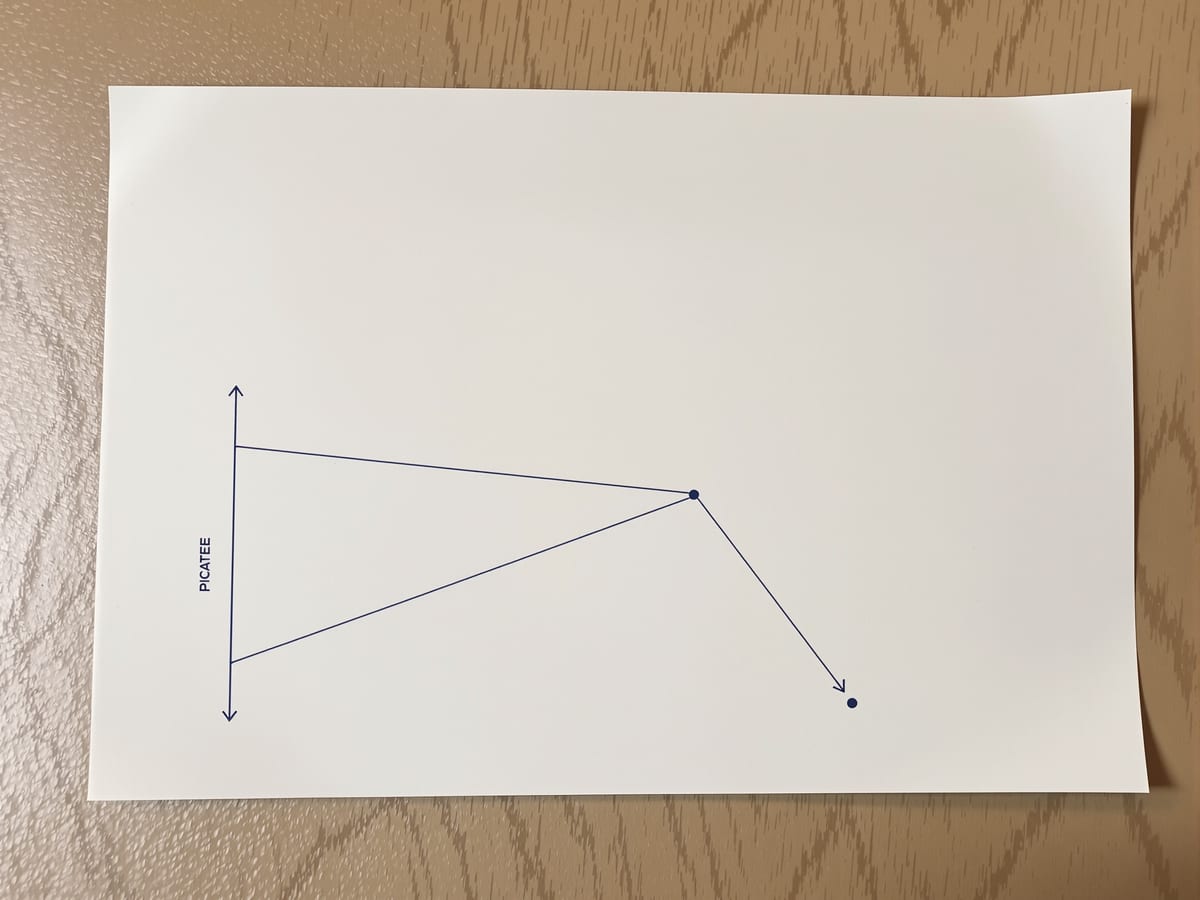
Parallel vs radiating projection
| Aspect | One | The other |
|---|---|---|
| How projectors behave | Parallel projectors — stay the same distance apart (orthographic and oblique) | Radiating sightlines — fan out from one station point (perspective) |
| What a single drawing shows | Multiview: one face at a time, true to measure, depth withheld | Perspective: many faces at once, depth vivid, measure lost |
| Measurability | Plans, sections and paralines can be scaled off directly | Perspectives cannot be reliably measured off the sheet |
| Point of view | Multiview and paraline assume no particular observer; the eye may roam | Perspective assumes an observer at a fixed point, looking one way |
| Best design use | Testing arrangement, proportion and construction logic | Testing atmosphere, arrival and the felt experience of space |
Key terms
The imaginary flat surface, sitting between the viewer and the object, onto which a three-dimensional subject is projected to make a drawing.
A picture ray running from a point on the object to the picture plane; how projectors behave defines the projection system.
A system in which projectors are parallel and meet the picture plane at right angles, keeping sizes constant with depth.
A system in which parallel projectors meet the picture plane at a slanted angle, letting one face stay true while others foreshorten.
A system in which sightlines fan out from a single station point, so parallels converge and distant things shrink.
A set of related orthographic views — plan, section, elevation — that together describe a form no single view can show.
A single pictorial view, such as a plan oblique or axonometric, in which parallel edges of the subject stay parallel on the sheet.
The relative width and density of a line, ranked heavy to very light to signal cut, edge, material change and layout.
Studio task
Take one small, familiar object — a chair, a study table, a staircase. Draw it four ways on a single sheet: a plan, an elevation, a simple plan-oblique paraline, and a quick freehand perspective. Beside each, write one line naming what that view shows clearly and one line naming what it hides. Then vary your line weights so the profile of anything cut reads heaviest. You will feel, directly, how each system steers what you notice.
Self-assessment
1. What single relationship distinguishes the three projection systems from one another?
2. Why must a three-dimensional subject usually be drawn as a set of multiview drawings rather than one orthographic view?
3. Which line weight is correct for the profile of what is cut in a section?
Recap
References & further reading
- [1]Francis D.K. Ching, Architectural Graphics (6th ed.). Hoboken: John Wiley & Sons, 2015.
- [2]Francis D.K. Ching, Design Drawing (3rd ed.). Hoboken: John Wiley & Sons, 2019.
- [3]Francis D.K. Ching, Architecture: Form, Space, and Order (4th ed.). Hoboken: John Wiley & Sons, 2014.
- [4]Robert W. Gill, Manual of Rendering with Pen and Ink. London: Thames & Hudson, 1984.
- [5]Rendow Yee, Architectural Drawing: A Visual Compendium of Types and Methods (4th ed.). Hoboken: John Wiley & Sons, 2012.
- [6]Bureau of Indian Standards, IS 962: Code of Practice for Architectural and Building Drawings. New Delhi: BIS.
Further reading
- Francis D.K. Ching, Architectural Graphics (6th ed.). John Wiley & Sons — the primary companion for every unit of this course.
Sources gathered and fact-checked June 2026. Published values vary by source, sample and method — treat as indicative and confirm against the cited standard before structural use.
Where this course goes next
You now have the map. The next unit zooms in on the drawings that carry almost every real project — the multiview building drawings: plans, sections and elevations, and the poché and line-weight discipline that make them read as space rather than as tangled lines.
The author
Amogh N P
Architect, interior designer, and creative polymath. Studio Matrx began in his notebooks — his vision of design made honest, useful, and open to everyone. Its Academy is written and taught in his memory, and free, forever.
More about Amogh →