
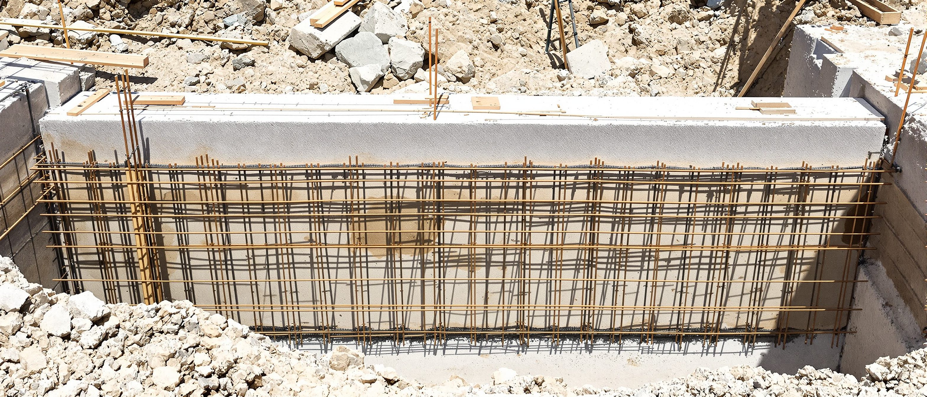
Foundation, Plinth & Structure
Setting out the footings, the DPC that stops damp, and drawing reinforcement.
The foundation plan is a setting-out drawing — the mason pegs the columns from it before any backfill, so it is dimensioned to the column grid, not wall faces. Learn the isolated, strip and raft footings; the plinth beam, filling and the all-important damp-proof course (DPC) at plinth level above ground; the column-footing junction with its L-bent dowels; and the conventions for representing RCC reinforcement — covers, hooks and the bar bending schedule. Explore the key figures with the construction-detail tool.
Learning objectives
By the end of this lesson, you will be able to — mapped to the course outcomes for Architectural Detailing and Working Drawing:
Draw a foundation plan as a setting-out drawing, dimensioned to the column grid.
Detail isolated/strip/raft footings, the plinth beam, filling and plinth protection.
Position and detail the DPC and anti-termite measures at plinth level.
Represent RCC reinforcement correctly — cover, hooks, dowels and the BBS.
Footings & reinforcement
The foundation plan sets out to the grid; the footing detail shows the pad, PCC, mesh and L-bent dowels with the right cover; and you represent the steel with hooks and a BBS.[1, 4, 5]
A setting-out drawing
Drawn looking down on the footings before backfill: the column grid, each footing marked (F1, F2…) and keyed to a schedule, the plinth-beam layout, and centre-to-centre dimensions for the mason to peg out. Levels of footing bottom and plinth-beam top are critical. Dimension to GRID CENTRES — columns must sit on the engineer's grid, not the wall faces.[1]
Plinth, DPC & anti-termite
The plinth beam ties the columns; the DPC at plinth level above ground stops rising damp; and anti-termite treatment plus plinth protection complete the defence.[2, 3, 5]
The base of the wall
The plinth beam is an RCC tie beam at plinth level connecting columns and carrying the superstructure wall — detail its section (e.g. 230×300 mm), bars and stirrups, and top RL at plinth. Below, the plinth filling is compacted earth/sand in layers, topped by a PCC bed and the ground-floor slab. Plinth height is commonly 450–600 mm above ground.[5]
Explore the details
Pick a junction — footing, DPC and more across the course — and read its key India-correct figures and detailing note.
Construction details · pick a junction
Isolated footing
Unit IIBottom mesh both ways; column dowels with a 90° L-bend resting on the mesh, lapping with column bars above.
Figures are India-correct standard practice — read the exact value off the relevant IS code / NBC for your case.
At a glance
| Aspect | One | The other |
|---|---|---|
| Soil | Isolated footing: good bearing | Raft: weak / low-bearing soil |
| Form | Isolated: discrete pads at columns | Raft: continuous slab under all |
| Reinforcement | Isolated: bottom mesh per pad | Raft: top & bottom mats overall |
| DPC | Myth: anywhere at the base | Reality: at plinth, ABOVE ground, full width |
| Cover | Footing: 50 mm | Column 40 · beam 25–30 · slab 15–20 mm |
Key terms
Plain Cement Concrete — an unreinforced levelling/blinding course below footings and floors.
Column bars anchored into the footing to splice with the column reinforcement above.
Damp-Proof Course — a horizontal barrier at plinth level stopping rising damp.
An RCC beam at plinth level tying the columns and supporting the walls.
The specified clear distance from a concrete surface to the nearest bar (footing 50, column 40).
Bar Bending Schedule — a table of bar mark, shape, size, length and quantity.
Studio task
Draw a foundation plan (dimensioned to the column grid) and a 1:20 isolated-footing section for a small framed building: show the pad, the PCC levelling course, the bottom mesh, the column dowels with their L-bend and lap, the cover (50/40 mm), and the plinth beam. On the wall section at plinth, position the DPC correctly above ground, full width, and note the anti-termite treatment.
Self-assessment
1. The DPC at plinth must be positioned —
2. Nominal cover to reinforcement in a footing per IS 456 is typically —
3. Column starter (dowel) bars in a footing should be detailed with —
Recap
References & further reading
- [1]BIS, IS 962 — Architectural and Building Drawings (foundation plan conventions).
- [2]BIS, IS 6313 — Anti-Termite Treatment in Buildings.
- [3]BIS, IS 3067 — design/construction of DPC; standard Indian plinth practice.
- [4]BIS, IS 456:2000 — Plain and Reinforced Concrete (cover, anchorage, splices).
- [5]SP 34 / IS 2502 — Handbook on Concrete Reinforcement and Detailing; Rangwala, Building Construction.
Further reading
- BIS — IS 456:2000 and SP 34 (Reinforcement Detailing).
- S.C. Rangwala — Building Construction (foundations, DPC, plinth).
- Francis D.K. Ching — Building Construction Illustrated.
Sources gathered and fact-checked June 2026. Published values vary by source, sample and method — treat as indicative and confirm against the cited standard before structural use.
The author
Amogh N P
Architect, interior designer, and creative polymath. Studio Matrx began in his notebooks — his vision of design made honest, useful, and open to everyone. Its Academy is written and taught in his memory, and free, forever.
More about Amogh →