
Residential MEP Coordination for Indian Architects
Electrical, Plumbing, and HVAC Coordination Through the Architect's Drawing Set
Residential MEP — mechanical, electrical, plumbing — is the least-loved layer of architectural drawing. Architects often hand off load calculation to the electrical consultant, fixture sizing to the plumbing consultant, and HVAC layout to the HVAC vendor, retaining only "coordination" as the architect's role. The result is predictable: a Stage 6 site where the AHU duct cannot pass under the beam, the kitchen waste line slopes the wrong way, and the wardrobe has no power point because the chase was missed.
The architect's MEP role is coordinator, not designer-of-record. But coordination is not a passive activity. It requires the architect to understand load logic, fixture-unit math, drainage gradients, sleeve coordination, and the geometric constraints that determine whether a duct can fit. This guide is the architect's working reference for those constraints — the level of MEP literacy required to specify a defensible drawing set at Stage 4.
"The architect coordinates. The engineer designs. Both fail when the architect tries to engineer or the engineer tries to coordinate." — Aphorism in mature design practices

1. The Architect's MEP Role
For a typical Indian residential project, three MEP sub-consultants are involved:
| Discipline | Consultant Role | Architect's Role |
|---|---|---|
| Electrical | Designs distribution, sizes circuits, specifies switchgear | Coordinates conduit routes, chase locations, lighting layout (RCP), DB position, earth-pit location |
| Plumbing | Sizes pipes, designs hot-water, specifies fittings | Coordinates wet-area locations, sleeve positions through slab, drain gradients |
| HVAC | Sizes capacity, designs ducting/refrigerant pipes | Coordinates indoor unit positions, ducting drops, outdoor unit locations, condensate routing |
In small residential projects (<200 sqm), there is often no MEP consultant — the architect coordinates directly with the contractor's plumber and electrician. In larger projects, sub-consultants produce design drawings; the architect overlays them on architectural drawings, identifies coordination conflicts, and issues integrated working drawings.
The coordination conflicts that recur:
- Electrical conduit clashing with plumbing pipe in a wall chase
- HVAC duct passing through a structural beam zone
- Drainage line falling below the slab into a habitable room below
- Light fixture position conflicting with HVAC supply diffuser
- DB (distribution board) position blocked by a wardrobe
The architect's drawing set is the place where these conflicts surface (or don't). A clean working-drawings set has layered MEP overlays on each plan; a sloppy one has architectural drawings only, with MEP drawings handed off as separate documents the contractor must reconcile on site.
2. Electrical — Load Estimation and Distribution
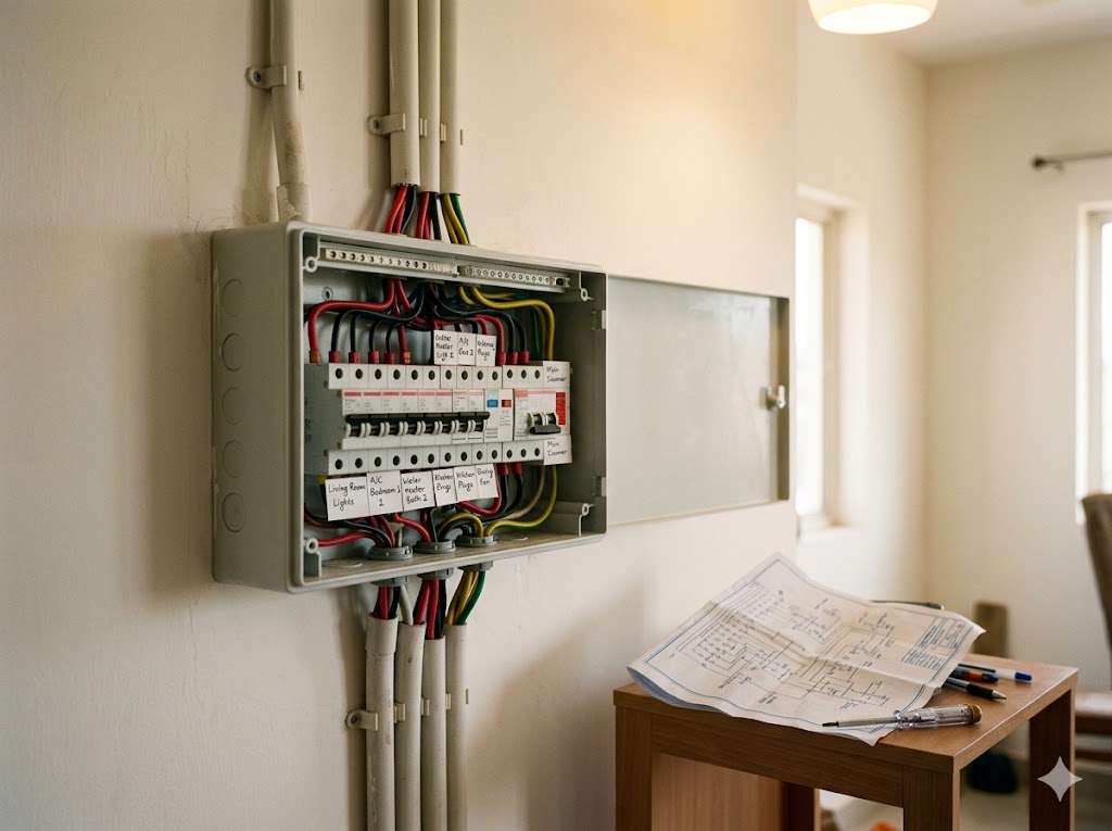

The architect does not size the connected load — that is the electrical consultant's job — but the architect must understand the load logic to coordinate DB position, riser shaft, and circuit count.
Connected Load — Indicative for Indian Residential
| Appliance / Circuit | Typical Connected Load (kW) |
|---|---|
| Lighting (full home, LED) | 0.5–2 |
| Fans | 0.3–0.8 |
| AC — split, 1.5 ton | 1.5 |
| AC — VRF/VRV per indoor unit | 0.8–2.0 |
| Geyser | 2 |
| Kitchen — induction hob | 3 |
| Kitchen — microwave | 1.2 |
| Kitchen — dishwasher | 2 |
| Refrigerator | 0.3 |
| Washing machine | 2 |
| TV / electronics | 0.3 |
| EV charger (Level 2 home) | 7.4 (single-phase) or 11 (three-phase) |
| Water pump (overhead) | 0.5–1 |
| Water heater (storage) | 2–3 |
| Lift (residential) | 5–8 |
Source: Indicative ratings consolidated from BIS IS 732 (Code of Practice for Electrical Wiring Installations) and manufacturer datasheets; supplemented by Indian residential practice norms.
Diversity factor: not every appliance runs at peak simultaneously. The demand load (what the supply must actually deliver) is typically 50–70% of connected load for residential.
A 3000-sqft villa with full appliance complement has a connected load of ~30–45 kW and a demand load of ~18–28 kW. This determines whether the supply is single-phase (up to ~7.5 kW residential, ~10 kW with permission) or three-phase (above that, mandatory three-phase). The architect coordinates with the consultant to position the service connection, energy meter, MCB DB(s), earth pit, and DG/inverter location — all of which need physical space and access.
"In residential MEP, single-phase to three-phase is the threshold above which the project is no longer a 'house' from the utility's perspective." — Practitioner observation
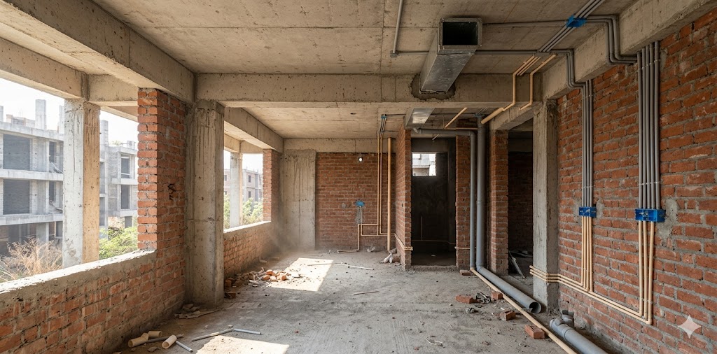
3. Conduit and Chase Planning
Electrical conduit runs through walls (chases) and slabs (sleeves). The architect's coordination decisions:
| Decision | Working Rule |
|---|---|
| Conduit OD vs wall thickness | A 25mm OD conduit needs 35–40mm chase depth in 230mm wall; in 115mm walls, route around or use surface conduit |
| Vertical chase rules | Permitted only at corners, not in mid-wall; depth not exceeding 1/3 of wall thickness; horizontal chases discouraged in load-bearing |
| Slab sleeves | Pre-cast, never chased after slab is poured; minimum 50mm above slab top to avoid cover damage |
| Switch board height | 1200mm AFFL standard; verify ergonomic for client (bedside switches at 600mm, kitchen above counter etc.) |
| DB / sub-DB position | Common circulation, typically near service room; not in bathroom, kitchen splash zone, or behind movable furniture |
| Earth-pit location | Outside building footprint, accessible for inspection, away from foundation |
The architect's drawing — the electrical layout plan — shows every switch, point, light, and fan with circuit references; the conduit layout drawing shows the actual conduit routes through walls and slabs, coordinated with structural and plumbing.
Most Indian residential contractor disputes at Stage 6 originate from missing information on one of these two drawings. Architects who produce both at Stage 4 — clearly, with circuit numbering matching the electrical schedule — have substantially smoother site execution than those who produce neither.
4. Plumbing — Fixture Units and Pipe Sizing

The architect does not size pipes (the plumbing consultant does), but the architect's working knowledge of fixture units (FU) under IS 1172 is what enables sensible wet-area coordination.
IS 1172 Fixture Units (FU) — Indicative
| Fixture | Cold Water FU | Drainage FU |
|---|---|---|
| Water closet (flush tank) | 5 | 4 |
| Wash basin | 1 | 1 |
| Bath tub | 4 | 2 |
| Shower | 2 | 2 |
| Kitchen sink (single) | 2 | 2 |
| Kitchen sink (double) | 3 | 3 |
| Dishwasher | 1 | 2 |
| Washing machine | 4 | 4 |
| Floor drain | — | 1 |
Source: Bureau of Indian Standards, IS 1172 (Code of Basic Requirements for Water Supply, Drainage and Sanitation), latest revision; cross-referenced against UPC 2018.
The plumbing consultant aggregates FU per branch and main, applies the IS 1172 lookup for pipe size at that flow rate, and produces the plumbing drawing. The architect's role:
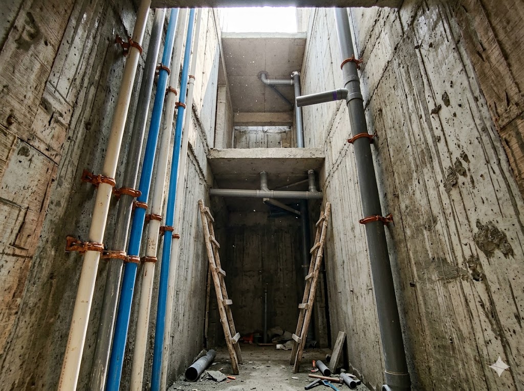
- Locate wet areas adjacent vertically across floors to enable common riser shafts (saves space, simplifies maintenance)
- Provide adequate riser shaft size — minimum 600 × 600 mm clear for residential, 900 × 900 mm preferred
- Avoid drainage runs across long horizontal distances — every 1 m of horizontal run requires gradient, which costs slab depth
- Coordinate floor traps and shower drains with floor finish levels — a shower without sufficient gradient ponds water
Drainage Gradients (IS 1742)
| Pipe Diameter | Minimum Gradient | Maximum Gradient |
|---|---|---|
| 100 mm (4") | 1:60 (1.7%) | 1:30 |
| 80 mm (3") | 1:50 (2%) | 1:25 |
| 50 mm (2") | 1:40 (2.5%) | 1:20 |
Source: Bureau of Indian Standards, IS 1742 (Code of Practice for Building Drainage); supplemented with BWSSB/MWSSB practice notes.
A 100 mm waste line falling 50 mm over 3 m horizontal run achieves the minimum gradient — but in the false-ceiling space, 50 mm is meaningful drop. The architect must allow it in the floor-to-floor section.
Pipe materials in Indian residential:
- CPVC for hot water — IS 15778, withstands 82°C continuous, 93°C intermittent
- UPVC / PVC for cold water — IS 4985, cheaper, lower temperature limit
- SWR-PVC for soil/waste — IS 13592, the dominant residential drainage choice today
- Cast iron (CI) for heavier residential / multi-storey — IS 1729, used where SWR is acoustically inadequate
- HDPE / PE for water tanks and pressurised supply — IS 12701 for tanks
5. Water Tank Sizing
The architect's working calculation for water-tank capacity:
Per-capita water demand (IS 1172): 135 LPCD (litres per capita per day) for residential without flushing-cistern; 155 LPCD with cistern.
Sizing convention: Underground sump = 1 day's demand; overhead tank = 1 day's demand. Together, 2 days' total reserve.
Worked Example
A 4-person family villa:
- Daily demand: 4 × 155 = 620 L/day
- Recommended underground sump: ~1000 L (with margin)
- Recommended overhead tank: ~1000 L (with margin)
- Total reserve: ~2000 L (>3 days at full occupancy)
Practical Indian residential sizing:
| Family / BHK | Sump (L) | Overhead (L) |
|---|---|---|
| 2-BHK family of 4 | 1000 | 1000 |
| 3-BHK family of 5 | 1500 | 1000 |
| 4-BHK family of 6 | 2000 | 1500 |
| Villa with garden / pool | +30–50% | +30–50% |
Tank materials: PE (HDPE) per IS 12701 is the dominant choice; RCC underground sumps are common for higher capacity; stainless-steel tanks are premium-tier. The architect coordinates tank position, ladder access, overflow drain, vent pipe, and inlet/outlet locations with the structural drawing — particularly for overhead tanks where the supporting structure is critical.
6. HVAC Coordination
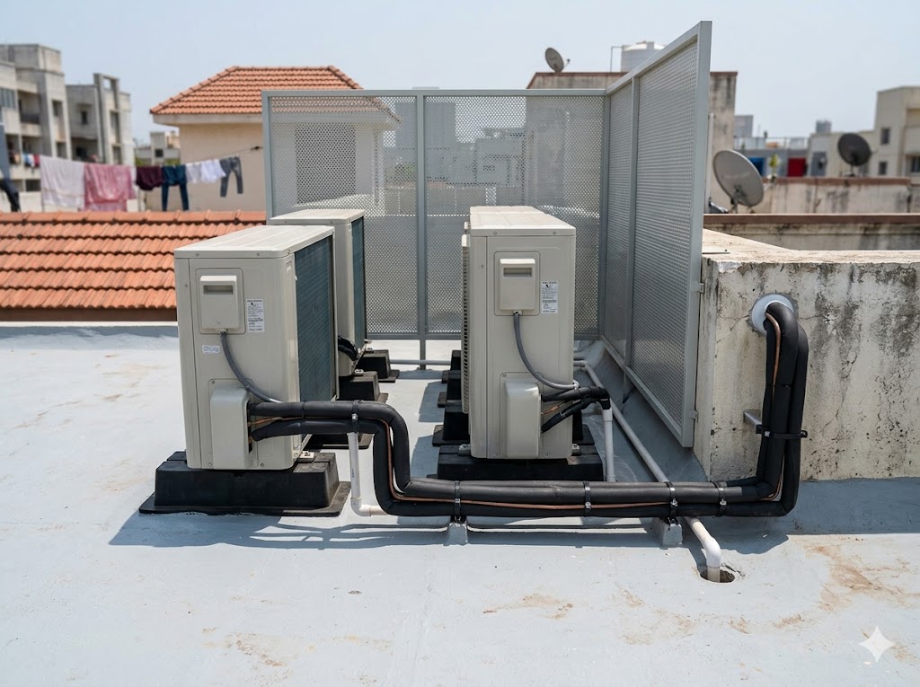

Residential HVAC in India is dominated by split AC and VRF/VRV systems. The architect's coordination decisions:
Split AC vs VRF — Architect's Decisions
| Question | Split AC | VRF / VRV |
|---|---|---|
| Number of outdoor units | One per indoor unit | One per zone (4–8 indoor units per outdoor) |
| Outdoor unit location | Outside each room — typically balcony or external wall | Common roof or service yard |
| Refrigerant piping | Short, direct | Long, branching — needs coordination through ceilings/shafts |
| Indoor unit type | Wall-mounted split | Cassette, ducted, wall-mounted, floor — flexibility |
| Architect's coordination effort | Per-room, simpler | Whole-house, complex but cleaner |
| Cost | Lower upfront | Higher upfront, lower lifecycle |
For residential >250 sqm, VRF is increasingly the default for premium projects, because it:
- Hides the outdoor units in one location (better elevation aesthetics)
- Allows ducted indoor units for clean ceilings (no wall-mount visible)
- Provides individual zone control with central scheduling
The architect's coordination drawings include:
- Indoor unit location plan — every cassette and ducted unit located on RCP
- Refrigerant pipe routing — typically in ceiling plenum, sometimes in shafts
- Condensate drain routing — must fall to an open drain or floor trap (often overlooked)
- Outdoor unit platform — structural support, acoustic insulation, weather protection
- Service access — every indoor unit needs a service hatch in the false ceiling
Common HVAC Coordination Failures
| Failure | Cause | Prevention |
|---|---|---|
| Duct cannot pass under beam | Beam depth eats false-ceiling clearance | Coordinate at Stage 3, not Stage 6; allow 350–450 mm plenum minimum |
| Outdoor unit on bedroom-window-facing balcony | Acoustics not considered | Locate outdoor unit on service yard or non-bedroom-adjacent face |
| Condensate drain stops mid-ceiling | No fall to drain | Trace condensate from each indoor unit to a verified drain point |
| Cassette positioned over a beam | Indoor unit needs service space; beam blocks access | Coordinate cassette positions with structural beam grid |
7. Sleeve and Block-Out Coordination Through Structure
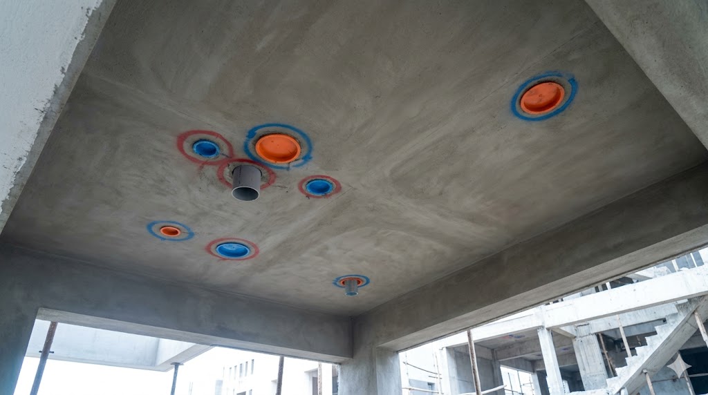

When pipes, ducts, or conduit must pass through structural slabs or beams, the architect coordinates sleeves and block-outs with the structural engineer. This must happen at Stage 4 — sleeves cannot be drilled through cast slab without compromising structure.
Sleeve Coordination Rules
| Service | Typical Sleeve Size | Coordination Note |
|---|---|---|
| Plumbing waste (100 mm) | 150 mm (with insulation/clearance) | Must align with riser shaft on each floor |
| Plumbing supply (50–80 mm) | 100 mm | Hot/cold separated typically |
| Electrical conduit cluster | 150 × 150 mm | Often a horizontal opening rather than circular |
| HVAC refrigerant + drain | 150 mm | Two pipes plus condensate |
| HVAC duct (residential) | Variable, can be large rectangular block-out | Structural engineer's input mandatory |
The architect's deliverable: a slab plan with sleeve locations marked on the structural drawing, signed off by both structural engineer and MEP consultant before slab casting. Without this, sleeves are punched after casting — losing structural integrity and creating the classic "core-cut residential slab" defect.
8. Drawing-Set Hygiene
A clean Stage 4 working-drawings set for residential includes the following MEP-related drawings:
Required MEP Drawing Set
| Drawing | Scale | What It Shows |
|---|---|---|
| Reflected Ceiling Plan (RCP) | 1:50 | Lights, fans, AC indoor units, ceiling level changes, exhaust, fire detectors |
| Electrical Point Layout | 1:50 | Switches, points, sockets, DB/sub-DB locations, circuit numbers |
| Conduit Layout | 1:50 | Conduit routes through walls and slabs |
| Plumbing Layout (per floor) | 1:50 | Hot/cold lines, drain branches, isolation valves, riser positions |
| Drainage Layout (per floor) | 1:50 | Floor traps, branches, gradient direction arrows |
| HVAC Layout | 1:50 | Indoor units, ducting, refrigerant piping, condensate runs |
| Structural Sleeve Plan | 1:50 | Block-outs and sleeves coordinated with MEP |
| Wet-Area Detail | 1:20 | Section through bathroom showing trap, drain, slope, waterproofing |
| MEP Schedule | Tabular | Every fixture, fitting, and luminaire by code, model, quantity |
The discipline is to produce all of these — even on small projects — because they are the architect's protection. When a Stage 6 dispute arises ("the contractor put the switchboard at 1500 mm instead of 1200 mm"), the architect's working drawings settle it in 30 seconds. Without the drawing, the dispute drags out and the architect's reputation absorbs the deviation.
"The architect who produces no MEP coordination drawing is the architect who chases the contractor through Stage 6." — Practitioner aphorism
9. The Architect's Closing Note
MEP coordination is not glamorous work. It does not appear on the architect's portfolio, it does not feature in client presentations, and it is invisible in every photograph the project ever generates. But it is the work that determines whether a residence functions for the next 30 years or generates service calls and complaints from year one.
The discipline — produce the layered MEP drawings at Stage 4, coordinate sleeves with structure, verify wet-area gradients, calculate diversity factors with the electrical consultant — adds 20–40 hours of senior-architect work per project. The cost saved in Stage 6 disputes, contractor reworks, and post-handover defect calls is multiples of that. And the practice that operates this way builds a reputation for the operational quality of its buildings that the alternative practices cannot.
Cross-References Within Studio Matrx
- Working Drawings & Documentation — the broader Stage 4 deliverable set
- Architectural Lighting Design for Indian Homes — RCP, fixture spacing, dimming protocols
- Medical Gases, Plumbing & Electrical Infrastructure for Healthcare — institutional MEP companion
- The Architect's Scope of Services in India — Stage 4 deliverables that include MEP coordination
- Architect's Site Supervision Checklist — Stage 6 routines to verify MEP execution
- Use the Lighting Planner to model lighting load and fixture spacing
- Use the Plumbing Pressure Test checklist to verify on-site plumbing
References
1. Bureau of Indian Standards (2019) IS 1172 — Code of Basic Requirements for Water Supply, Drainage and Sanitation. New Delhi: BIS.
2. Bureau of Indian Standards (2019) IS 1742 — Code of Practice for Building Drainage. New Delhi: BIS.
3. Bureau of Indian Standards (2019) IS 732 — Code of Practice for Electrical Wiring Installations. New Delhi: BIS.
4. Bureau of Indian Standards (2014) IS 12701 — Rotationally Moulded Polyethylene Water Storage Tanks. New Delhi: BIS.
5. Bureau of Indian Standards (2017) IS 15778 — CPVC Pipes and Fittings. New Delhi: BIS.
6. Bureau of Indian Standards (2013) IS 13592 — SWR-PVC Pipes for Soil and Waste Discharge. New Delhi: BIS.
7. Bureau of Indian Standards (2018) IS 4985 — UPVC Pipes for Potable Water Supplies. New Delhi: BIS.
8. Bureau of Indian Standards (2016) National Building Code of India 2016, Part 9 (Plumbing Services). New Delhi: BIS.
9. International Association of Plumbing and Mechanical Officials (2018) Uniform Plumbing Code 2018 (UPC). Ontario, CA: IAPMO.
10. American Society of Heating, Refrigerating and Air-Conditioning Engineers (2024) ASHRAE Handbook — HVAC Applications. Atlanta: ASHRAE.
11. Energy Conservation Building Code (2017, 2024 updates) ECBC Residential — Eco-Niwas Samhita — Mechanical Provisions. New Delhi: BEE.
12. Indian Society of Heating, Refrigerating and Air-Conditioning Engineers (ISHRAE) Residential HVAC Practice Notes.
Author's Note: MEP literacy is one of the highest-leverage competencies an Indian architect can cultivate. The math is simple, the codes are stable, and the coordination discipline is teachable. This guide is a desk reference for the architect's coordination role; the Studio Matrx tools support specific MEP calculations (water-tank sizing, fixture-unit aggregation, rainwater-harvesting demand) at site-specific resolution.
Disclaimer: This article is for informational and educational purposes only. It does not constitute professional MEP-engineering advice. Load values, fixture-unit conventions, gradient targets, and HVAC capacity rules cited are indicative of current Indian practice but may vary in specific applications. Architects must verify against current IS, NBC, and ECBC standards and consult qualified MEP consultants before final specification. Studio Matrx, its authors, and contributors accept no liability for decisions based on this guide.
Interactive · MEP coordination stack
Active: HVAC duct + insulation
Co-ordination note
Largest service — drives the false-ceiling height. Plan duct routing FIRST.
Typical depth: 250 mm in plenum
Conflicts with
- ⚠ Water supply (PEX/CPVC)
- ⚠ Soil/waste drain (PVC)
- ⚠ Electrical conduit + tray
- ⚠ Fire sprinkler + detection
Export this guide
Related Guides — Deep-dive reading
Scope Boundaries — Architect, Interior Designer & Contractor
The Architects Act 1972, the IIID Code, BOCW 1996 & RERA 2016 — Stage-by-Stage Role Map, Hot Boundary Zones, Liability Matrix, and the Tri-Party Contracting Discipline for Indian Residential Practice
ConstructionDesigning Adaptable & Universal-Design Homes
Accessibility, Aging-in-Place, and the Multi-Stage Family — Code, Anthropometrics, and Plan-Stage Discipline for Indian Residential Architects
Room PlanningPlumbing Drawings Explained
Water in, waste out — how to read supply lines, drainage and vents, the symbols and line types, slopes and traps, shafts and the sunken-slab logic that keeps your bathroom dry.
Construction DrawingsRelated Tools — Try Free
Rainwater Tank Sizer
How big should your rainwater tank be? Computes annual harvest, recommended tank capacity in litres, water-bill savings, and payback — for 10 Indian cities.
RWH CalculatorFalse Ceiling Cost Estimator
Live ₹/sqft across 8 ceiling types — POP, gypsum, designer, metal, PVC, wooden — with cove and spot lighting for 20 Indian cities.
Cost CalculatorCross-Ventilation Analyzer
Estimate airflow and air changes per hour (ACH) from room size, window areas, layout, and local wind — with NBC 2016 Part 8 compliance check.
Ventilation Calculator