
Medical Gases, Plumbing & Electrical Infrastructure for Healthcare
An Architect's Working Reference — Central Medical Gas Pipeline (NBC Part 8 + IS 7902), LMO Yard and Manifold, Hot-Water 60°C Demand, Dual-Stack Drainage, UPS Critical Loop, DG Sizing, Earthing, Water Treatment, and the Healthcare Services Architectural Toolkit
Medical gases, plumbing, and electrical infrastructure together constitute the services architecture of a healthcare building — the systems that deliver oxygen to a ventilator, hot water to a CSSD, UPS-backed power to an OT, and earthing to a microsurgical microscope. These systems are designed by specialist consultants but provisioned by the architect — service shafts, plant rooms, equipment yards, vertical risers, ceiling voids, structural penetrations, fire-rated separations, monitoring infrastructure. A hospital where the services architecture has been thoughtfully provisioned at concept stage operates reliably; one where services were "added later" suffers chronic operational issues that cost the institution years of frustration.
This guide is the eighth in the design-focused series and the second of the services pair. It assumes the reader has read the pillar regulatory reference, the regulatory deep-dives, the preceding design articles, and particularly the companion HVAC guide. Together those two guides cover the architect's services responsibilities in healthcare.
The guide is organised by service: medical gases first (oxygen, nitrous oxide, medical air, vacuum, AGSS, carbon dioxide, instrument air, nitrogen), then plumbing (water demand, hot water, drainage, special applications), then electrical (incoming HT, substation, DG, UPS, critical/non-critical loops, earthing). Each service is covered with the architectural-provisioning lens: where does the equipment go, how big should the room be, what shafts are needed, what loading does the structure see, how does the architecture support reliable operation.
"In a hospital, electrical reliability is patient survival reliability. Three minutes without UPS in an OT can be three minutes too many." — D.K. Sarin (b. 1948), former Director HSCC India, paraphrased
"Medical gas is invisible until it isn't. The day the oxygen pressure drops in an ICU is the day the architecture is judged on a decision made years earlier." — Anonymous senior healthcare engineer, paraphrased
1. Medical Gas Pipeline Architecture
Medical gases — oxygen, nitrous oxide, medical air, vacuum, carbon dioxide, AGSS (anaesthetic gas scavenging), and (in some hospitals) instrument air and nitrogen — are delivered through a piped network from central sources to outlets at every point of use. The architecture provisions the source yard, the manifold room, the riser shafts, and the outlet placement.

Gases — sources and central plant
| Gas | Use | Central Source |
|---|---|---|
| Oxygen (O₂) | Patient breathing; resuscitation | LMO (Liquid Medical Oxygen) tank + cylinder backup; or PSA generator + cylinder backup |
| Nitrous Oxide (N₂O) | Anaesthesia (decreasing use) | Cylinder manifold |
| Medical Air (4 bar) | Anaesthesia, ventilator | Compressor + dryer + filter; redundant; cylinder backup |
| Surgical Air (7 bar) | Pneumatic surgical tools | Compressor; separate from medical air |
| Vacuum | Suction in OT, ICU, ward | Vacuum pump + receiver + filter; redundant |
| Carbon Dioxide (CO₂) | Laparoscopy insufflation | Cylinder manifold |
| AGSS (Anaesthetic Gas Scavenging) | Removes waste anaesthesia gases from OT | Vacuum-based scavenging line; vented to roof |
| Instrument Air (oil-free) | Some specialty applications | Oil-free compressor |
| Nitrogen (N₂) | Some surgical tools (orthopaedic) | Cylinder manifold |
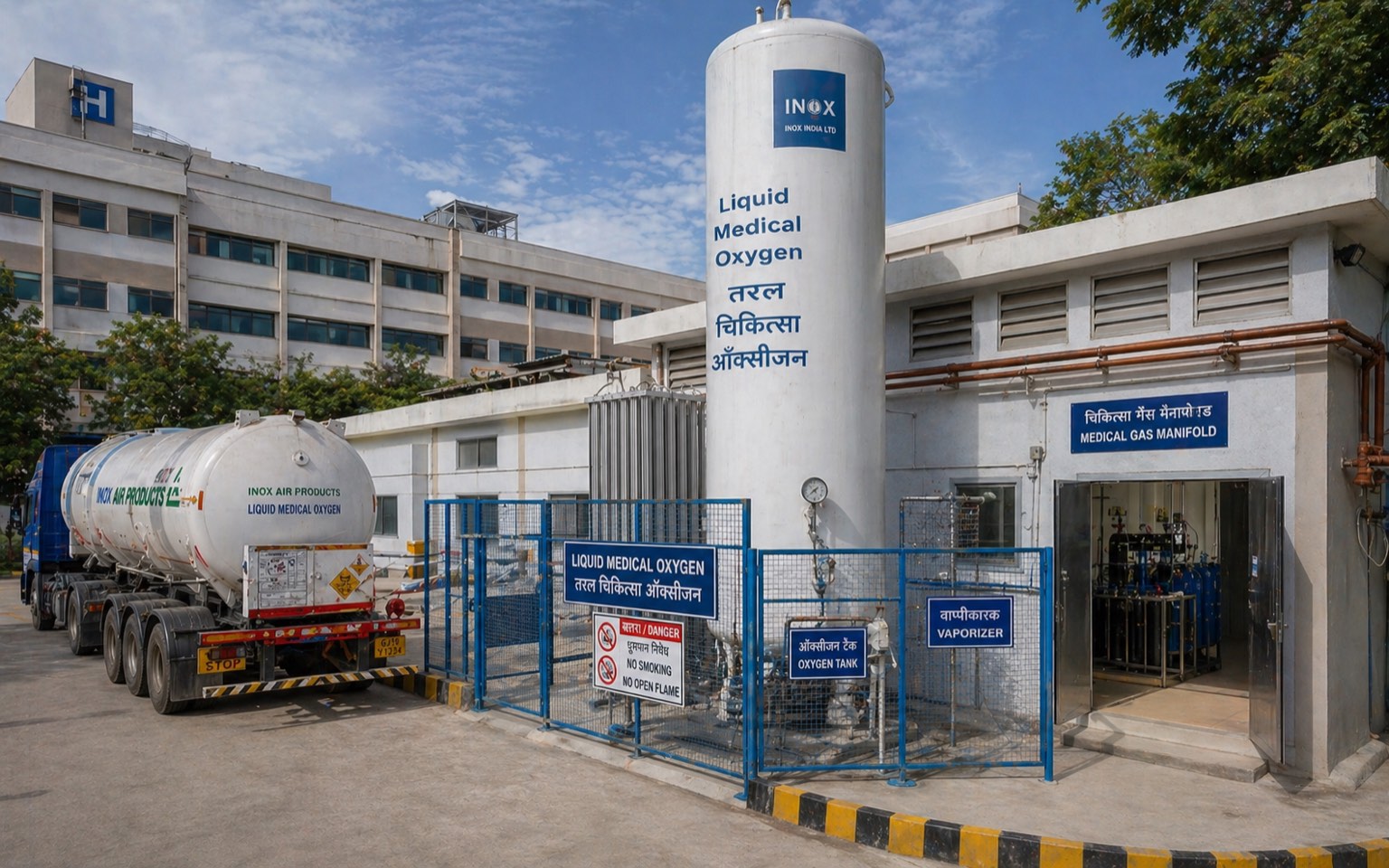
LMO yard — architectural provision
| Element | Specification |
|---|---|
| Tank capacity | Sized for 7-day consumption + 50% buffer; typical 13 m³ for 100-bed; 25 m³ for 200-bed; 50 m³ for 500-bed |
| Yard area | 60–90 m² for 100-bed; 100–140 m² for 200-bed; 200+ m² for 500-bed |
| Tank set-back from building | 6 m minimum (PESO); 9 m preferred |
| Tank set-back from boundary | 3 m minimum (PESO) |
| Yard surface | Concrete; bonded to earth |
| Fencing | Steel mesh, 2 m high, lockable gate |
| Vehicle access | Tanker turning circle 9 m radius; reverse-in possible |
| Vapouriser | Adjacent to tank; ambient or steam-heated |
| Pipe routing | From vapouriser to manifold room |
| Lightning protection | Earthed; surge protection on outgoing pipe |
| Fire protection | Hydrant within 30 m; manual call point at gate |
| Signage | "No smoking", "Oxygen", "Authorised personnel only"; bilingual |
Manifold room — architectural provision
| Element | Specification |
|---|---|
| Room area | 12–18 m² for 100-bed; 25–40 m² for tertiary |
| Location | Adjacent to LMO yard or alternate gas source; near service shaft |
| Equipment | Manifolds for cylinder backup (O₂, N₂O, CO₂, N₂); pressure regulators; alarm panel |
| Ventilation | 6 ACH; independent exhaust; alarm on low pressure |
| Fire-rated | 2-hour separation from main building |
| Pipe entry | Sealed; through dedicated wall penetration |
| Cylinder storage | Strapped vertical; 5–10 cylinder capacity |
| Floor finish | Anti-static; sealed |
| Lighting | LED; emergency-backed |
| Door | Fire-rated; lockable; vision panel |
Pipeline distribution architecture
| Element | Specification (NBC Part 8 + IS 7902) |
|---|---|
| Pipe material | Medical-grade copper; certified seamless or DIN 1987; degreased |
| Pipe joints | Brazing with silver filler; pressure-tested |
| Pipe identification | Colour-coded per IS 7902; labelled at every metre |
| Vertical risers | Dedicated shaft; sealed at floor penetrations |
| Horizontal mains | Above ceiling; supported per piping standard |
| Branch lines | To zone shutoff valves |
| Zone shutoff valves | At each ward entry, OT entry, ICU entry; identifiable |
| Outlets at point of use | NIST or DIN; gas-specific; tested |
| Outlet density | Per OT: O₂×2, Air×2, N₂O×1, Vacuum×3; Per ICU bed: O₂×2, Air×1, Vacuum×3; Per ward bed: O₂×1, Vacuum×1 |
| Pressure | 4 bar at outlets (medical air, oxygen, N₂O); 7 bar (surgical air); 50 kPa (vacuum) |
| Alarm panels | At each shutoff zone; central master at manifold room; nurse station alarm |
| Pressure monitoring | Continuous; BMS-integrated |
| AGSS | Separate vacuum line; vented to roof; not connected to general vacuum |
The architectural provision: dedicated medical gas riser shaft per zone, sized at minimum 600 × 600 mm; outlet placement schedule per room as part of GFC drawings; manifold and LMO yard sized at concept stage.
2. Plumbing — Water Demand and Hot Water

Water demand schedule for a 100-bed hospital (typical)
| Use | Demand (litres/bed/day) | 100-bed Total (KLD) |
|---|---|---|
| Drinking + cooking | 5–10 | 0.5–1.0 |
| Patient bathing | 100–150 | 10–15 |
| Family / attendant | 50–80 | 5–8 |
| Toilet flushing | 30–50 | 3–5 |
| Laundry | 80–120 | 8–12 |
| CSSD / OT cleaning | 30–50 | 3–5 |
| Kitchen | 30–50 | 3–5 |
| HVAC make-up (cooling tower, humidification) | Varies; 50–100 | 5–10 |
| Cleaning / housekeeping | 30–50 | 3–5 |
| Landscape | Varies | 2–5 |
| Total | 408–660 | 40–70 KLD |
A 100-bed hospital therefore needs roughly 50 KLD water supply; 200-bed ~100 KLD; 500-bed ~250 KLD.
Architectural provision:
| Element | Specification |
|---|---|
| Underground water tank — domestic | 3-day demand + fire reserve = 200 m³ for 100-bed |
| Overhead water tank | 1-day demand = 50 m³ for 100-bed; on roof or structural truss |
| RO / softener plant | If hard water (most Indian sites); ~ 8–15 m² plant room |
| Booster pumps | Plant room ~ 9–12 m²; redundant pumps |
| Main distribution shaft | Vertical riser 600 × 600 mm dedicated |
| Floor distribution | Above ceiling; manifold per ward |
| Hot water generation | Centralised boiler / heat-pump / solar-augmented; 60°C delivery; sized for peak demand |
| Hot water re-circulation | Continuous loop; insulated |
| Cold water | Insulated to prevent condensation |
| Fixture-level mixing | Thermostatic mixing valve at point of use; 38–42°C delivery |
| Backflow prevention | At every connection to public main |
| Water meter / leak detection | At main; at zone |
Hot water demand and 60°C requirement
NABH and infection-control protocols require hot water ≥ 60°C at point of generation to control Legionella and other pathogens. Mixing valves at fixture deliver safe 38–42°C to prevent scalding.
| Hot water use | Temperature at use |
|---|---|
| Hand-wash | 38–42°C |
| Patient bathing | 42°C |
| Laundry | 60°C (washing) |
| CSSD / dishwasher | 65–82°C |
| OT scrub | 38°C |
Architectural plant: central hot-water generator (boiler / heat-pump / solar-thermal) at basement or rooftop; insulated re-circulating loop throughout; thermostatic mixing valves at fixtures.
Drainage architecture
| Drainage Stream | Architectural Provision |
|---|---|
| Soil + waste (general) | 100–150 mm vertical stack; vented at top |
| Patient toilets | Dedicated risers; trapped at every fixture |
| OT / ICU drains | Trapped; disinfection point; separate stack from general |
| Kitchen | Grease trap upstream; separate stack |
| Laundry | Separate stack; lint trap |
| Mortuary | Disinfection at source; separate stack |
| Pathology / lab | Separate stack; pre-treatment for chemicals |
| Imaging — film developer (legacy) | Silver recovery; separate handling |
| Dialysis effluent | Separate stack; chemical content monitored |
| Floor drain — wet areas | Sloped floor; trapped; UV / disinfection at high-risk |
| Roof / terrace rainwater | Dedicated stack; recharge / harvest |
| ETP / STP feed | Separate underground main to plant |
The architect provides the drainage layout drawing with stack locations, vent terminations, and special-handling streams. Crossing of soil/waste with medical gas / electrical / data is avoided via separate shafts.
Sluice room architecture
| Element | Specification |
|---|---|
| Area | 4–6 m² per ward unit |
| Sink | Sluice / hopper for body fluid disposal; flush + spray |
| Bedpan washer | Wall-mounted; thermal disinfection 80°C+ |
| Floor finish | Welded vinyl; coved skirting; floor drain |
| Walls | PVC panel or epoxy |
| Ventilation | 10 ACH; negative pressure |
| Door | Self-closing; lockable |
3. Electrical Infrastructure — Critical-Care Reliability
Hospital electrical reliability is patient-survival reliability. The architecture provisions a hierarchy of supply: HT (high-tension) incoming, LT (low-tension) distribution, DG (diesel generator) backup, UPS (uninterruptible power supply) for critical loads.

HT incoming and substation
| Element | Specification |
|---|---|
| HT incoming voltage | 11 kV typical (some 33 kV for tertiary) |
| HT load | 100-bed: 500–800 kVA; 200-bed: 1000–1500 kVA; 500-bed: 2500–4000 kVA |
| Substation area | 30–60 m² for 100-bed; 60–100 m² for 200-bed; 100–200 m² for 500-bed |
| Substation location | Ground floor; separate building or fire-rated within main |
| Transformer | 11 kV/415 V; cooling-oil filled or dry-type |
| Transformer separation | 6 m setback from building (oil-filled); fire-rated wall (dry) |
| HT/LT panels | In substation; segregated |
| DG synchronisation | Auto-transfer switch (ATS) |
| Earthing | Dedicated earth pit; separate from neutral and lightning |
| Lightning protection | Roof-level; earthing pit |
| Substation ventilation | Cross-ventilated; or AC for sealed substation |
| Substation access | External direct; service vehicle access |
DG sizing
| Hospital | DG Capacity | Notes |
|---|---|---|
| 100-bed | 500–625 kVA (1 unit) + redundancy optional | Auto-start within 10 sec |
| 200-bed | 750–1000 kVA (2 units in parallel) | N+1 redundancy |
| 500-bed | 1500–2500 kVA (2–3 units N+1) | Critical-loop dedicated |
| Tertiary 1000-bed | 4000–6000 kVA | N+1 with separate critical loops |
DG architectural provision:
| Element | Specification |
|---|---|
| DG room area | ~ 1 m² per kVA (for housing only); 30 m² minimum for 500 kVA |
| Acoustic enclosure | Mandatory for DG > 50 kVA outside DG room |
| Fire compartmentation | 4-hour rated separation from main building |
| Ventilation | Forced; sized for combustion air + cooling |
| Exhaust | Stack height per CPCB (30 m for > 800 kW) |
| Fuel storage | Day tank (200–500 L) inside DG room; bulk tank external (1000–10,000 L) |
| Bulk tank set-back | 6 m + from building (PESO); bunded |
| Auto-transfer switch | At substation |
| Synchronisation panel | If parallel DG |
UPS and critical-load loop
| UPS Application | Capacity | Backup Time |
|---|---|---|
| OT critical loads (lights, anaesthesia, monitor) | 25–40 kVA per OT | 60 min |
| ICU critical loads | 20–30 kVA per 6-bed ICU | 60 min |
| Server / data centre | Sized to load | 30+ min |
| Fire alarm | Per panel | 24+ hrs (battery) |
| Emergency lighting | Per circuit | 2 hrs (battery) |
UPS architectural provision:
- UPS room 12–18 m² near substation
- Battery room separate (acid fumes); ventilated
- Cabling segregated — UPS feeds direct to critical circuits without crossing non-UPS
Earthing and lightning protection
| System | Earthing Provision |
|---|---|
| Body earth (electrical equipment) | < 1 Ω; separate pit |
| Neutral earth | < 1 Ω; separate pit |
| Lightning earth | < 10 Ω; separate pit |
| Equipotential bonding | OT, ICU, MRI room |
| MRI cage earthing | RF cage continuous earth |
| Patient bedside earth | OT, ICU isolated earth (low-impedance) |
| BMS / data earth | Star-point earth |
Architectural provision: dedicated earthing pits at perimeter; vertical earth conductors in shafts; equipotential bonding ring at OT/ICU floor level.
Critical-loop circuit segregation
| Load Type | Power Source |
|---|---|
| Critical (OT, ICU, fire alarm) | Mains + DG + UPS |
| Essential (general lighting, lifts, water pumps) | Mains + DG |
| Non-essential (HVAC, kitchen, laundry, admin) | Mains only (DG optional) |
The architect's electrical drawings distinguish these three circuits — colour-coded — and the building's distribution panels are physically separated to prevent cross-contamination.
4. Special Applications — Dialysis Water, MRI Power, Imaging UPS

Dialysis water treatment (haemodialysis)
| Stage | Specification |
|---|---|
| Pre-filter | 20 μm sediment |
| Carbon filter | Dechlorination |
| Water softener | Sodium ion exchange |
| Reverse osmosis | Two-stage; AAMI / ISO 13959 quality |
| Storage tank | Stainless steel; UV-sterilised |
| Distribution loop | Continuous re-circulating; PEX or PVC sanitary |
| Dialysis chair tap | Quick-disconnect |
| Water testing | Endotoxin, bacteria, hardness — daily / weekly |
Water plant area for a 12-chair dialysis centre: 18–25 m².
MRI room electrical / RF
| Element | Specification |
|---|---|
| RF Faraday cage | Continuous copper / steel; door RF-tight; viewing window RF-screened |
| Magnetic field exclusion | 5-gauss line marked; equipment / personnel restrictions inside |
| Quench vent | From cryostat to roof; minimum 10 cm diameter |
| Magnet delivery route | Removable wall panel or roof access |
| Power | Dedicated transformer; clean ground |
| RF filters at penetration | All cables, pipes filtered through cage |
Imaging UPS
CT, cathlab, mammography, and other imaging equipment require dedicated UPS (typically vendor-supplied) plus building UPS for monitor and display. The architect coordinates room electrical with vendor specification.
5. The Architect's Services Toolkit
| # | Step | Output |
|---|---|---|
| 1 | Programme review — outlets per room, gas, plumbing | Services brief |
| 2 | Medical gas — LMO yard sizing, manifold location | LMO + manifold plan |
| 3 | Medical gas — outlet schedule per room | Outlet schedule |
| 4 | Medical gas — riser shafts and zone valves | Riser layout |
| 5 | Plumbing — water demand calculation | Water demand schedule |
| 6 | Plumbing — UG / overhead tank sizing | Tank schedule |
| 7 | Plumbing — hot water plant + re-circulation | Hot water scheme |
| 8 | Plumbing — drainage stack layout | Drainage scheme |
| 9 | Plumbing — special applications (dialysis, mortuary, kitchen) | Special drainage |
| 10 | Electrical — HT load and substation sizing | Substation scheme |
| 11 | Electrical — DG sizing and room | DG scheme |
| 12 | Electrical — UPS critical loop | UPS scheme |
| 13 | Electrical — earthing and lightning | Earthing scheme |
| 14 | Critical / essential / non-essential circuit segregation | Distribution scheme |
| 15 | BMS integration for gas, plumbing, electrical | BMS scope |
| 16 | Fire-rated separations for plant rooms | Compartmentation drawing |
| 17 | Acoustic isolation for DG, plant | Vibration / sound scheme |
| 18 | Service shaft sizing and sealing | Shaft schedule |
| 19 | Maintenance access — every plant | Access provision |
| 20 | Commissioning brief — gas, water, power | Commissioning schedule |
6. Common Services Failure Modes
| # | Failure | Prevention |
|---|---|---|
| 1 | LMO yard set-back inadequate | 6 m PESO from concept |
| 2 | Manifold room without independent ventilation | 6 ACH; alarm on low pressure |
| 3 | Medical gas outlet density inadequate | NABH-aligned schedule |
| 4 | Zone shutoff valves absent | Per ward/OT/ICU |
| 5 | Hot water below 60°C at generation | Boiler / heat-pump sized for 60°C |
| 6 | RO water plant absent for hard-water site | 18–25 m² plant room |
| 7 | Drainage stacks merged across streams | Separate stacks per stream |
| 8 | OT/ICU drains via general stack | Dedicated stack + disinfection |
| 9 | Mortuary effluent without disinfection | Disinfection at source |
| 10 | DG sizing under-spec | 100% essential + 50% non-essential margin |
| 11 | UPS sizing under-spec for OT/ICU | Per-OT 25–40 kVA |
| 12 | Earthing combined (body + neutral + lightning) | Separate pits |
| 13 | Battery room without ventilation | Acid fumes vented |
| 14 | Acoustic — DG noise > 75 dB at boundary | Acoustic enclosure |
| 15 | DG fuel storage insufficient | 3-day diesel reserve minimum |
| 16 | Substation in fire-prone location | Fire-rated separation; clearance |
| 17 | MRI quench vent incorrectly routed | Vent to roof, all-weather |
| 18 | Dialysis water plant under-spec | AAMI quality + 1.5x capacity |
References
- ANSI/AAMI (2014) AAMI RD 52: Dialysate for Hemodialysis. Arlington: AAMI.
- ASHRAE (2019) ASHRAE Handbook — HVAC Applications: Health-Care Facilities. Atlanta: ASHRAE.
- Bureau of Indian Standards (2016) National Building Code of India 2016, Part 8 — Building Services. New Delhi: BIS.
- Bureau of Indian Standards (2003) IS 7902: Pipeline Distribution System for Medical Gases — Code of Practice. New Delhi: BIS.
- Bureau of Indian Standards (2007) IS 14665: Electric Traction Lifts — Code of Practice. New Delhi: BIS.
- Bureau of Indian Standards (1991) IS 3043: Code of Practice for Earthing. New Delhi: BIS.
- Bureau of Indian Standards (2003) IS 15301: Hydraulic Design of Fixed Fire Protection Systems. New Delhi: BIS.
- Central Pollution Control Board (2018) DG Set Emission Standards. New Delhi: CPCB.
- Facility Guidelines Institute (2022) Guidelines for Design and Construction of Hospitals. St. Louis: FGI.
- IEC (2017) IEC 60364-7-710: Low-Voltage Electrical Installations — Medical Locations. Geneva: International Electrotechnical Commission.
- ISO (2017) ISO 13959: Water for Haemodialysis and Related Therapies. Geneva: ISO.
- Joint Commission International (2020) International Standards for Hospitals. 7th edn. Oakbrook Terrace: JCI.
- Joshi, D.C. and Joshi, M. (2018) Hospital Administration. 2nd edn. New Delhi: Jaypee Brothers.
- NABH (2020) Standards for Hospitals, 5th Edition. New Delhi: NABH.
- Petroleum and Explosives Safety Organisation (2016) Static and Mobile Pressure Vessels (Unfired) Rules 2016. Nagpur: PESO.
- US Environmental Protection Agency (2010) Drinking Water and Health. Washington: EPA.
- World Health Organization (2008) Essential Environmental Health Standards in Health Care. Geneva: WHO.
- World Health Organization (2017) Guidelines for Drinking Water Quality. 4th edn (with first addendum). Geneva: WHO.
Author's Note: Services architecture is the half of healthcare design that the architect provisions but does not personally engineer. The architect's discipline is to engage MEP consultants from the brief stage and ensure that building decisions support the services strategy. Indian projects routinely mis-provision services — undersized substations, wrong-located LMO yards, mixed drainage stacks, inadequate UPS — because the architect treated services as a downstream MEP problem. This guide establishes the provisioning method that produces hospitals that operate reliably from day one. The remaining four guides in this design-focused series cover specialty typologies, sustainability, and the business of healthcare commissions.
Disclaimer: This article is for informational and educational purposes only and does not constitute professional architectural or engineering advice. Services design depends on specific project parameters and must be done by qualified MEP / electrical / mechanical engineers in coordination with the architect. Studio Matrx, its authors, and contributors accept no liability for decisions made on the basis of the information in this guide.
Interactive · Medical-gas outlet checker
Major OT (modular) · 10 outlets across 6 gases
Outlet layout (schematic bedhead panel)
Required outlets
- O₂2× Medical oxygen4.1 bar
- MA2× Medical air (compressed)4.1 bar
- VAC3× Medical vacuum (suction)−40 to −60 kPa
- N₂O1× Nitrous oxide (anaesthesia)4.1 bar
- AGSS1× Anaesthetic Gas Scavenging System−1.0 kPa
- CO₂1× Carbon dioxide (laparoscopy)4.1 bar
Position
Ceiling pendant + wall (anaesthesia side); duplicate at head end.
Spec notes
BIS-spec colour-coded outlets, fail-safe shutoff valves outside OT.
References: IS 13450 (medical gas piping), HTM 02-01 (UK guidance widely used), NABH 5th ed. Always verify with biomedical engineer + plumbing consultant before issue.
Export this guide
Related Guides — Deep-dive reading
Building Plumbing Services Guide (India): MEP-Grade Water, Drainage & Riser Design
A professional, India-first reference to plumbing engineering for larger and commercial buildings — integrated design with MEP, multi-storey water distribution, and drainage and venting stacks.
PlumbingHigh-Rise Plumbing Systems (India): Pressure Zoning, Boosters & Tall Stacks
A professional, India-first deep dive into plumbing for towers and multi-storey buildings — the pressure problem, vertical pressure zoning, break-pressure tanks, hydro-pneumatic and booster pumps, pressure-reducing valves, and tall soil, waste and vent stacks with offsets.
PlumbingPandemic Preparedness & Isolation Hospital Design in India
An Architect's Working Reference — AIIR Negative-Pressure Rooms · Cohort Isolation Wards · Surge-Conversion Architecture · Triage & Screening Layers · COVID-19 Lessons · BSL-3 Sample Rooms · Mortuary Surge Capacity · The Pandemic-Ready Hospital Master Plan
Healthcare ArchitectureRelated Tools — Try Free
Acoustic Privacy (STC) Visualizer
Indian healthcare acoustic visualizer — compare wall assemblies and noise sources, see received SPL after STC attenuation, and check FGI 2018 / IS 1950 / NABH speech-privacy compliance with live dual-canvas waveform.
Acoustic ToolRainwater Tank Sizer
How big should your rainwater tank be? Computes annual harvest, recommended tank capacity in litres, water-bill savings, and payback — for 10 Indian cities.
RWH CalculatorMaterial Schedule Generator
Generate a room-wise finish schedule — walls, floors, ceilings, trim, and joinery by location.
Material Schedule