

Coordinate Geometry
The grid behind every plan — points, distance, and setting out.
Under every plan is a grid. Each point — a corner, a column, a doorway — has an address: its coordinates. Master that simple idea and you hold the thread that runs from a sketch, through a CAD model, to the exact spot a wall is built on site.
Learning objectives
By the end of this lesson, you will be able to — mapped to the course outcomes for Building Materials & Construction I:
Plot points on the cartesian plane and name its axes and quadrants.
Use the distance, midpoint and slope formulas.
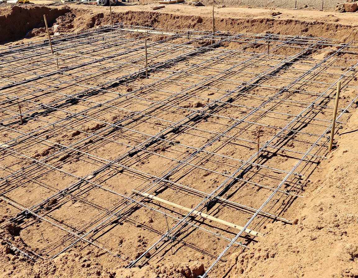
Explain how coordinates drive CAD/BIM and on-site setting-out.
Extend the idea to 3D coordinates (x, y, z).
The coordinate plane
Two axes, an origin, and every point as an ordered pair (x, y). From two points you can find the distance, the midpoint and the slope between them — try it below.[1]
Distance, midpoint & slope
d = √((x₂−x₁)² + (y₂−y₁)²) · M = ((x₁+x₂)/2, (y₁+y₂)/2) · m = (y₂−y₁)/(x₂−x₁)
Where coordinates run architecture
Coordinates are not abstract — they are the backbone of drawing and building. Select an application.
CAD & BIM
Every line, wall and window in a CAD or BIM model is stored as x, y, z coordinates. Drawing is, underneath, coordinate geometry.[3]


Self-assessment
1. The distance between (x₁,y₁) and (x₂,y₂) is:
2. A total station on site primarily measures:
3. A point in 3D space is defined by how many coordinates?
Recap
References & further reading
- [1]Coordinate geometry — the cartesian plane, distance, midpoint and slope (standard formulas). CK-12 / Britannica. https://flexbooks.ck12.org/cbook/ck-12-cbse-math-class-10/
- [3]Total station → CAD/BIM coordinate workflow and setting out. KOREC; Bench-Mark surveying. https://www.korecgroup.com/guides/how-to-use-a-total-station-for-setting-out/
Further reading
- A standard engineering-mathematics / coordinate-geometry text (e.g. NCERT/CBSE Class 10–12 coordinate geometry; B.S. Grewal, Higher Engineering Mathematics).
- Dutta, B.N. & Dutta, S. Estimating and Costing in Civil Engineering. New Delhi: CBS Publishers (for setting-out & measurement).
Sources gathered and fact-checked June 2026. Published values vary by source, sample and method — treat as indicative and confirm against the cited standard before structural use.
The author
Amogh N P
Architect, interior designer, and creative polymath. Studio Matrx began in his notebooks — his vision of design made honest, useful, and open to everyone. Its Academy is written and taught in his memory, and free, forever.
More about Amogh →