

MRI · CT · PET-CT Shielding & Imaging Suite Design in India
An Architect's Working Reference — RF Cage for MRI · Helium Quench Vent · Lead Shielding for CT · AERB Type-2 Approval · PET-CT Hot Lab and Uptake Rooms · Cyclotron-Radiopharmacy GMP · Hybrid OR & Cath Lab · Mobile Imaging Truck Pads · The Imaging Department Master Plan
Imaging is the most regulatorily-dense and architecturally specialised cluster of rooms in any hospital. A 200-bed tertiary hospital in India has roughly 12% of its built-up area allocated to imaging — but the imaging suite carries 40%+ of the regulatory complexity, 30%+ of the equipment cost, and the highest density of architectural specifications per square metre of any department in healthcare. Each modality — diagnostic X-ray, CT, MRI, mammography, fluoroscopy/cath lab, PET-CT, nuclear medicine, cyclotron — has its own hazard, its own shielding requirement, its own AERB approval timeline, its own room schedule, and its own equipment-coordination intricacy. The architect designing an imaging department is, in effect, designing seven different architectural problems simultaneously, each with manufacturer-specific constraints, each with regulator-specific approval lead times, and each with consequences for the wider hospital plan if mis-located.
This guide is a facility-type deep-dive in the Studio Matrx healthcare architecture series. It extends the existing AERB compliance for radiology and imaging guide with deeper modality-by-modality coverage. It assumes the reader has read the pillar regulatory reference, is familiar with NBC 2016 Group C, and has reviewed the cancer hospital guide (which addresses LINAC bunker design, the most regulatorily-heavy ionising-radiation typology). Here we focus on what is specific to diagnostic and interventional imaging — the four-modality classification and architectural responses, the AERB approval stack per machine type, the CT scanner room as the workhorse, the MRI room as the most complex, the PET-CT suite as the most specialised, the cyclotron facility, the interventional zone, the imaging department master plan, the failure modes that recur across Indian projects, and the pre-design audit framework.
The position this guide takes is specific: imaging architecture is not "lay out the manufacturer's room and shield it". It is the integrated architecture of structural performance (vibration sensitivity, equipment loading), envelope performance (RF cage for MRI, lead shielding for ionising), service redundancy (UPS, chiller, helium fill, radioactive plumbing), regulatory compliance (AERB, PNDT, NABH), patient experience (waiting, prep, post-scan recovery), and equipment lifecycle (10–15 year replacement cycles requiring access provision). The architect who treats imaging as a specialist subcontract delivers a hospital where the imaging department works at 60% capacity and the radiologists complain about every detail. The architect who internalises the modality-specific brief delivers a hospital where the imaging is a primary clinical instrument, not a constraint.
"The MRI room is not a hospital room with a magnet in it. It is a magnet with a hospital room around it. The architecture must respect the magnet, not the other way round." — Dr. Bhavna Bhargava (b. 1965), neuroradiologist, paraphrased from a 2018 site-survey orientation
"In imaging, the architect's gift is to make the equipment invisible to the patient and indispensable to the radiologist. The path between these two is narrow, technical, and requires intimate knowledge of every machine." — Ar. Sanjay Mohe (b. 1955), Bengaluru architect, paraphrased from a 2015 lecture on hospital design
1. Why Imaging is its Own Typology
Six characteristics make imaging distinct from general clinical typology:
- Modality-specific hazards. Each modality has a different hazard profile: scatter X-ray (general radiology + CT), magnetic projectile + helium quench (MRI), positron γ at 511 keV (PET-CT), neutron + γ activation (cyclotron). The architectural responses are not interchangeable.
- AERB approval is the gating activity. AERB pre-application at concept stage; layout approval before construction; survey + license after installation. Mis-sequencing this is the single most common cause of imaging-suite delay in Indian hospital projects.
- Equipment is purchased, not specified. Imaging equipment has 10–25 year procurement contracts (Siemens, GE, Philips, Canon, Hitachi). Each manufacturer has slightly different room dimensions, anchor patterns, service requirements, and shielding performance. The architecture must be coordinated with the specific equipment supplier from preliminary design.
- Vibration is a clinical specification. CT scanners require Vibration Criterion VC-A; MRI requires VC-D (the most stringent); microsurgery requires VC-B. Locating an MRI without vibration analysis produces image-quality issues that no operational fix can resolve.
- Lifecycle replacement is part of the brief. Equipment lifecycle is 10–15 years for major modalities. Architectural access for replacement (removable wall panel, equipment-access slab) must be designed in. Post-construction, replacement requires breaking walls if access was not provided.
- The patient experience is unusual. Patients spend 5–60 minutes per scan, often immobile, often anxious, often claustrophobic (especially for MRI). The room finishes, lighting, audio, and waiting infrastructure are part of the clinical brief — better-designed imaging rooms improve image quality by reducing patient motion.
The composite effect is that imaging architecture is a hybrid of physics, equipment-supplier coordination, regulatory work, and patient hospitality. No other clinical department demands this combination at this density.
2. The Four Modality Families
Imaging modalities cluster into four hazard families, each with distinct architectural responses.

Family 1 — X-ray and CT (ionising photons; diagnostic 80–150 kVp). Hazard: scatter radiation. Shielding: lead-equivalent 1.5–2.5 mm Pb at walls, doors, viewing windows. Approval: AERB Type-2 (registration); 3–4 month lead. Room area: X-ray 18 m²; CT 30–40 m². Indian count: ~70,000 X-ray installations, ~10,000 CT scanners. Most common imaging modality at every Indian hospital.
Family 2 — MRI (non-ionising magnetic; 1.5T or 3T typical). Hazard: magnetic projectile (any ferrous object becomes a projectile in proximity to the magnet); helium quench (sudden boil-off of liquid helium = up to 250 m³ helium gas in seconds). Shielding: RF Faraday cage (copper or galvanised); magnetic isolation; 5G line containment. Approval: state health department registration (no AERB — non-ionising); 2 month lead. Room area: 35–50 m² magnet room + 12 m² console + 12 m² technical room. Most architecturally demanding single modality.
Family 3 — PET-CT and nuclear medicine (ionising; positron / γ from radioisotopes). Hazard: patient becomes a radioactive source post-injection (60–90 min); high-energy γ at 511 keV (PET) or 140 keV (Tc-99m for SPECT). Shielding: lead-equivalent 6–9 mm Pb; hot lab thicker; inter-room separation between uptake rooms. Approval: AERB Type-1 (license, not registration); SC-MED-3 code; 4–6 month lead. Suite area: 35 m² PET-CT scanner + 12 m² hot lab + 3–5 × 8 m² uptake rooms + recovery + delay tank. Tertiary-only typology, growing rapidly in India.
Family 4 — Cyclotron and on-site radiopharmacy (particle accelerator; 11–18 MeV). Hazard: neutron + γ activation; activated air. Shielding: 3–4 m concrete (LINAC-bunker class — heaviest in healthcare). Approval: AERB Type-1 special; 8–12 month lead. Vault area: 30–40 m² + GMP radiopharmacy + QC lab + hot waste storage. National-tier only — approximately 25 facilities in India.
Boundary cases.
- Ultrasound (USG) — non-ionising; no AERB approval; PC-PNDT registration mandatory. Architectural deliverable: PNDT signage strategy, Form-A display at each USG room.
- Mammography — Family 1 (ionising) but with lighter shielding requirement. AERB Type-2.
- DXA bone density — Family 1 (ionising) but very light shielding; often combined with X-ray room.
- Fluoroscopy / cath lab / interventional radiology — Family 1 (ionising) but with sustained beam-on times; heavier shielding (2.0–2.5 mm Pb) and dedicated control rooms.
3. The AERB Approval Stack — Per Imaging Modality
Each imaging modality has a specific AERB code and approval pathway. The architect must know which applies to which machine and the lead time for each.

The approval-pathway matrix:
| Modality | AERB Code | Approval Type | Lead Time | Architect's Deliverable |
|---|---|---|---|---|
| General X-ray | SC-MED-2 | Type-2 (registration) | 2–3 months | Shielded room layout |
| CT scanner | SC-MED-2 | Type-2 (registration) | 3–4 months | Shielded room + barrier calc |
| Mammography | SC-MED-2 | Type-2 (registration) | 2–3 months | Shielded room (lighter Pb) |
| Cath Lab / IR / Fluoroscopy | SC-MED-2 | Type-2 (registration) | 3–4 months | Shielded room + control room |
| DXA (bone density) | SC-MED-2 | Type-2 (registration) | 2 months | Lighter shielding |
| MRI 1.5T / 3T | No AERB (non-ionising) | State health dept registration | 2 months | RF cage + Gauss-line plan |
| PET-CT (delivered FDG) | SC-MED-3 | Type-1 (license) | 4–6 months | Shielded suite + uptake plan |
| SPECT / Gamma camera | SC-MED-3 | Type-1 (license) | 4–6 months | Hot lab + uptake |
| Cyclotron + radiopharmacy | SC-MED-3 special | Type-1 + GMP | 8–12 months | Vault + GMP suite + QC |
| USG (any) | PC-PNDT (not AERB) | District CMO registration | 1 month | Form-A signage strategy |
Type-2 (registration) vs Type-1 (license). Type-2 registration is essentially declarative: the facility registers the equipment with AERB, submits the shielded-room layout and barrier calculation, and (subject to compliance) is registered. Type-1 licensing is more involved: the facility applies for a license, submits a detailed application including site plan, layout, RSO appointment, training records, and is licensed only after AERB site inspection. Type-1 is required for any facility involving radioactive sources (sealed or unsealed) — PET-CT, SPECT, brachytherapy, cyclotron.
Sequencing rule. AERB pre-application at concept stage: confirms the layout principle. Layout approval before construction: verifies the shielded room design. Survey and license after installation: verifies the as-built shielding meets the calculated specification. Each step is gating; mis-sequencing delays the entire commissioning calendar.
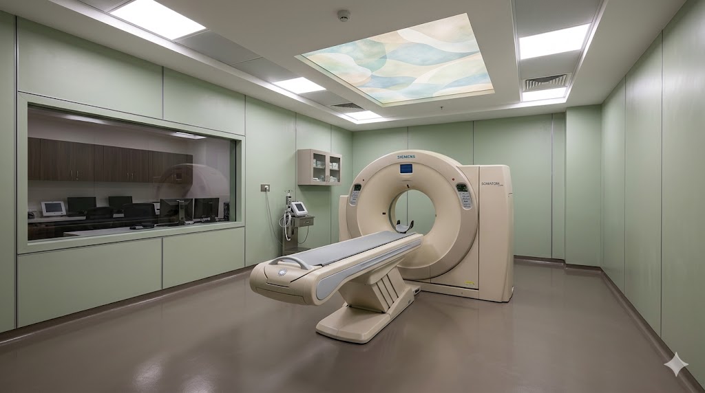
4. The CT Scanner Room
The CT scanner is the workhorse of Indian hospital imaging. Every secondary+ hospital has one; tertiary hospitals have 2–4; comprehensive cancer centres have 4–8. The architecture is well-established, but the details matter.

Schedule of accommodation:
| Element | Specification |
|---|---|
| CT scanner room area | 30–40 m² (36 m² benchmark; 6 × 6 m clear) |
| Clear ceiling height | 3.0 m minimum |
| Walls — shielding | 1.5–2.0 mm Pb-equivalent (gypsum-and-lead composite or solid lead sheet); per barrier calculation |
| Door — shielding | 1.5 mm Pb-clad; door interlock with beam-on |
| Lead-glass viewing window | 2.0 mm Pb-equivalent; 0.6 × 0.4 m typical; viewing height for seated operator |
| Floor finish | Standard (vinyl or epoxy); vibration VC-A target |
| Vibration target | VC-A — generally achievable on RCC slab; structural coordination at preliminary design |
| Console room | 14 m² adjacent; lead-glass viewing into scanner room; 2-monitor workstation |
| Equipment / technical room | 12 m² adjacent or below; CT chiller, UPS (100 kVA dedicated), PACS server connection |
| Patient changing alcove | 4–6 m² inside scanner room (curtained); chair |
| Equipment cabinet | Inside scanner room; for emergency cart, contrast supplies |
| Patient waiting | Pre-scan + post-scan; 4–6 seats outside the scanner room |
| Reporting room | Adjacent or in same wing; 2+ radiologist reading stations; low ambient light (100 lux); calibrated 5MP medical-grade displays |
Critical specifications:
- Manufacturer-specific anchor pattern. Each CT manufacturer (Siemens, GE, Philips, Canon) specifies a different floor anchor pattern. This must be in the structural drawings as a cast-in anchor plate at the slab pour stage — retrofitting anchors after construction is poor practice. Get the manufacturer's site-planning guide at concept stage.
- Vibration coordination. CT requires VC-A (1000 μm/s²). On an RCC structure, this is generally achievable with standard slab thickness. Critical: do not locate the CT scanner above or below an MRI (vibration pollution from MRI gradient coils to CT) or above/below high-traffic floors.
- UPS for the CT. Each CT scanner requires 80–100 kVA UPS for image-acquisition continuity during power transient. The UPS must be in the technical room; 15-minute runtime minimum.
- Cooling and chiller. CT generates significant heat; dedicated chiller in the technical room with manufacturer-specified cooling capacity (typically 30–50 kW per scanner).
- PACS connectivity. Network connection to hospital PACS via gigabit ethernet; latency < 50 ms target.
- Patient comfort. The CT room is not a "shielded vault"; it is a patient-occupied clinical room. Soft warm lighting (3000K, dimmable), pleasant wall finish, ceiling treatment with calming pattern (not aggressive), audio for patient breath-hold instructions. These soft architectural details improve image quality by reducing patient motion.
Throughput sizing. A single CT scanner running 12-hour single-shift can scan 30–60 patients per day depending on study mix (chest CT 10 min/study; cardiac 30–45 min/study; CT angiography 20 min/study). Two-shift operation reaches 80–120/day. The bunker count is set by patient throughput, not by hospital bed strength.
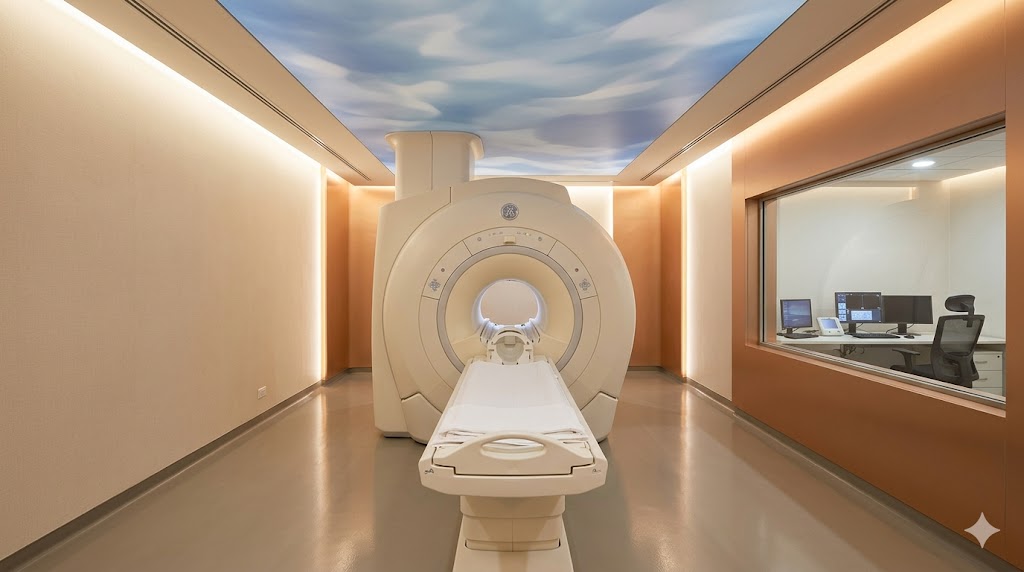
5. The MRI Suite — RF Cage, Helium Quench Vent, Gauss-Line Zoning
The MRI suite is the most architecturally complex single room in any hospital. Three integrated architectures must align: structural (vibration), envelope (RF Faraday cage), and services (helium quench vent and Gauss-line zoning).

Magnet room schedule:
| Element | Specification |
|---|---|
| Magnet room area | 35–50 m² (40 m² benchmark for 1.5T; 50 m² for 3T) |
| Clear ceiling height | 3.0 m minimum (MRI systems require minimum 2.7 m clear; 3.0 m comfortable) |
| Vibration target | VC-D (most stringent in healthcare; 250 μm/s²); requires structural floor isolation in many cases; HVAC fan and lift placement minimum 15 m from magnet |
| Magnetic field interior | Up to 30,000+ Gauss at isocentre (1.5T); 5 Gauss line within room (manufacturer-specified) |
| Faraday RF cage | Copper or galvanised steel; sealed at all penetrations; door + window + waveguides; tested at handover for 60 dB attenuation minimum |
| Helium quench vent | 200–300 mm diameter pipe direct to roof; NO 90° bends; pressure-tested; 250 m³ helium-gas capacity |
| Door | RF-tight (waveguide-treated); door interlock with magnet on |
| Window (control room) | RF-treated lead-glass or polycarbonate; 0.6 × 0.4 m typical |
| Floor finish | Sealed epoxy or sheet vinyl (non-magnetic) |
| Fire suppression | Water-mist or pre-action sprinkler; non-magnetic head; Inergen gas alternative |
| Cryogen makeup | Annual liquid-helium refill via dedicated access route; ferromagnetic-free path |
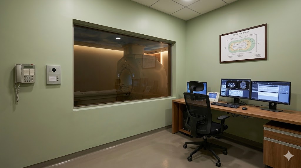
Console + technical room schedule:
| Element | Specification |
|---|---|
| Console room | 12–14 m²; RF-treated viewing window into magnet; 3-monitor workstation |
| Equipment / technical room | 12 m²; gradient cabinet, RF amplifier, UPS (200 kVA dedicated, 30-minute minimum) |
| Cryogen storage | 6–8 m²; ferromagnetic-free; 100–200 L liquid helium typical |
Patient-prep schedule:
| Element | Specification |
|---|---|
| Patient prep room | 12–14 m²; changing × 2; non-ferrous lockers |
| Screening / metal-check station | 4 m²; ferromagnetic-detection wand; final metal sweep before Zone IV entry |
The three integrated architectures:
Architecture 1 — Structural (vibration). MRI VC-D target requires RCC slab thickness 250–350 mm minimum, plus consideration of dynamic loads (HVAC fans, lifts, footfall, road traffic). For 3T MRI, dedicated vibration-isolated floor pad may be necessary. Structural-engineer coordination at concept is the only solution; retrofit isolation is prohibitively expensive.
Architecture 2 — Envelope (Faraday RF cage). The cage is a continuous conductive enclosure (typically 1.5 mm copper sheet or galvanised steel mesh) surrounding the magnet room on all six sides. All penetrations (doors, windows, ducts, conduits, waveguides) must be RF-sealed. The cage is supplied by a specialist subcontractor (Lindgren, ETS-Lindgren, or Indian licensee) and must be tested at handover for 60 dB attenuation across the operating frequency range (typically 64 MHz for 1.5T, 128 MHz for 3T).
Architecture 3 — Services (helium quench vent + Gauss-line). Helium quench is a low-probability but catastrophic event: sudden boil-off of the liquid helium (typically 1,500–2,000 L) into gaseous form (250+ m³). The quench vent is a 200–300 mm diameter pipe that takes this gas direct to the roof, with no 90° bends and no penetrations. The vent must be pressure-tested at handover. Gauss-line zoning: the 5 Gauss line is the boundary at which iron objects start to feel the magnetic pull; the 5 Gauss line should be entirely within the magnet room. The 1 Gauss line is the maximum permissible at any public boundary (lift, corridor, occupied office) — typically 4–6 m from the magnet for 1.5T, 6–9 m for 3T.
Manufacturer site survey. Every MRI installation requires a site survey by the equipment manufacturer at preliminary design stage. The site survey produces the magnet-specific Gauss-line plot, the quench-vent calculation, the structural anchor pattern, and the service-connection diagram. This must be commissioned before detailed design; many Indian projects have ordered MRI equipment without the site survey and discovered Gauss-line conflicts post-construction.
6. The MRI Safety Zones — ACR Four-Zone Architectural Model
Beyond the magnet-room architecture, the entire MRI suite is organised into four concentric access-control zones per the ACR Manual on MR Safety. The architecture enforces the boundary at every transition.

The four zones:
| Zone | Function | Access | Architectural Boundary |
|---|---|---|---|
| I — Public | Reception, waiting | No restriction | Standard internal door |
| II — Transitional | Patient prep, change, screening, history | Supervised | Standard internal door; reception controls flow |
| III — Restricted | Console, technical room | Approved staff only | Card-access door; staff badge; final metal screen |
| IV — Magnet room | Inside Faraday cage | Final screening required | RF-tight door; lockable; supervised; final ferromagnetic check (wand + visual sweep) |
The architectural translation:
- Zone I → II transition. Standard door; reception controls patient flow.
- Zone II → III transition. Card-access door (badge or key); ferromagnetic-detection wand; final metal sweep (oxygen tank, scissors, hair pins, mobile phones — common projectile incidents).
- Zone III → IV transition. RF-tight door (waveguide-treated); lockable from console side; supervised entry only; the final boundary.
Critical signage and safety infrastructure:
- "Quench warning" sign at every Zone III/IV door (warns of helium gas evolution and oxygen displacement risk in the unlikely event of quench)
- Emergency quench button accessible from console and from inside magnet room (for absolute emergency only — destroys the magnet)
- "NO CARDIAC PACEMAKER · NO METAL IMPLANTS · NO LOOSE METAL" signage at every Zone III/IV door, in English and state regional language
- Emergency oxygen monitor in magnet room (warns of helium displacement in case of quench)
Architecture is the first line of MRI safety. Operational vigilance backs it up. But the architecture sets the floor — a building that does not enforce the four-zone boundary by design will see operational drift over time.
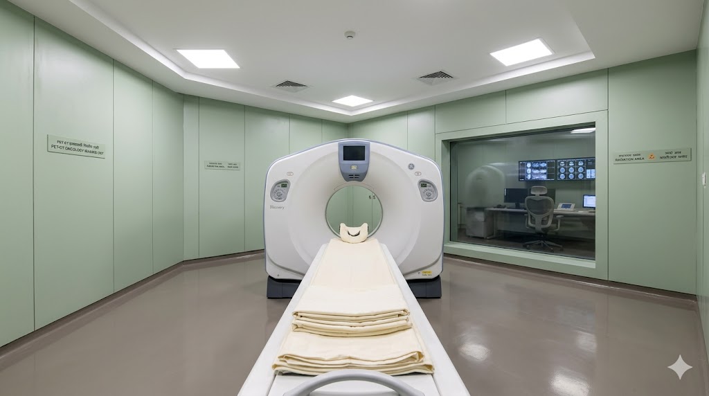
7. The PET-CT Suite
PET-CT requires the most specialised single suite in diagnostic imaging. The architectural challenge: the patient is the radioactive source for 60–90 minutes after injection, and the architecture must accommodate this fundamentally different relationship between patient and clinical space.

Patient flow (six stations):
1. Check-in — vitals, weight (for FDG dose calculation)
2. Injection — FDG by syringe in lead-shielded syringe-shield in the injection room
3. Uptake — 60–90 minute isolation in a dedicated uptake room; patient is the radioactive source
4. Scan — PET-CT scanner room; 30–45 minutes per study
5. Recovery — decay observation; patient still hot but lower activity
6. Discharge — hydration counselling; 18-hour avoidance of close contact with children/pregnant women
Suite components:
| Element | Specification |
|---|---|
| Reception + clean waiting | 30 m²; pre-injection patients (cold) |
| Check-in / vitals | 8 m²; weight, pulse, temperature |
| Hot lab | 12 m²; lead-shielded; hot fume hood with HEPA exhaust; dose calibrator; storage well; refrigeration; assay station |
| Injection room | 10 m²; lead-shielded; patient receives FDG via syringe shield |
| Uptake rooms | 3–5 × 8 m² each; reclining chair; TV; lead-shielded between rooms (10 mm Pb interroom) |
| PET-CT scanner room | 35 m²; 6 mm Pb-equivalent walls; gantry + couch |
| Console | 12 m²; adjacent to scanner |
| Recovery (hot) | 16 m²; for decay observation; 3–4 reclining chairs |
| Patient toilet (hot) | 6 m²; radioactive plumbing to delay tank |
| Delay tank | Below-grade; sealed concrete; capacity 10× decay-half-life of longest isotope |
| Hot waste storage | 6 m²; for sharps and used isotope vials; decay storage |
Total PET-CT suite footprint: 110–150 m² for a single-scanner unit.
The radioactive plumbing. F-18 (FDG) has a 110-minute half-life; radioactive waste decays to background in approximately 18 hours (10× T½). Tc-99m has a 6-hour half-life; waste decays in approximately 60 hours. The architectural deliverable: a dedicated sealed concrete delay tank (not connected to main sewer) that holds patient toilet waste, injection-room sink waste, and hot-lab sink waste for 10× the longest isotope half-life. After decay confirmation by assay, the tank discharges to the main STP. The delay tank is mandatory for AERB Type-1 license; missing it is the most common architectural failure in PET-CT projects.
The hot zone / cold zone separation. Pre-injection patients are in the cold zone (reception, waiting, check-in). Post-injection patients are in the hot zone (injection, uptake, scanner, recovery). The two zones must be physically separated; the architectural deliverable is two access paths and clear signage.
Cyclotron-attached vs delivered FDG. Most Indian PET-CT facilities use delivered FDG from a regional radiopharmacy (Mumbai, Delhi, Bangalore, Kolkata, Chennai have suppliers). This simplifies the architecture significantly — only the PET-CT scanner room and ancillary spaces are required, not the cyclotron. In-house cyclotron is justified only at very high volume (15+ scans/day) or at sites distant from a radiopharmacy.
8. The Cyclotron Facility (In-House FDG Production)
Where in-house FDG production is justified, the cyclotron facility adds significant architectural commitment. Approximately 25 cyclotron facilities operate in India as of 2026, primarily at apex national institutes (AIIMS Delhi, Tata Memorial, RMRC, BARC) and a few large private hospitals.
Cyclotron facility schedule:
| Element | Specification |
|---|---|
| Cyclotron vault | 30–40 m²; 4 m clear height; 3–4 m concrete shielding (LINAC-bunker class); below-grade preferred for shielding cost |
| GMP radiopharmacy | 20–30 m²; ISO 5 hot cell + ISO 7 background; pharmaceutical-grade air handling |
| QC lab | 12 m²; FDG release testing (radiochemical purity, sterility, endotoxin) |
| Hot waste storage | Decay storage for 10× half-life; activated waste handling |
| Activated air vent | Cyclotron operation activates room air; vent through HEPA + delay loop |
| Heavy crane | For target replacement and major service |
| Equipment maze | Cyclotron-target servicing access (3-turn maze pattern similar to LINAC) |
Total cyclotron facility footprint: 200–400 m² depending on isotope mix and scale.
The architectural complexity. The cyclotron is heavier (in shielding terms) than a LINAC because the neutron flux during operation activates wall materials, room air, and even the target. The shielding calculation must include neutron capture and γ activation — not just direct beam attenuation. The activated-air vent must include sufficient delay loop for short-lived activation products to decay before discharge. The GMP radiopharmacy must comply with both AERB (radiation safety) and Indian pharmacopeia (pharmaceutical-grade production for patient use). The dual regulatory approval is the most demanding in healthcare architecture.
The architect's role. A cyclotron commission requires specialist consultants: a medical physicist for shielding, a radiopharmacy specialist for GMP, an HVAC engineer for activated-air management. The architect's role is to coordinate these — the vault location, the GMP suite layout, the QC lab adjacency, the hot waste route, and the integration with the broader hospital plan. A cyclotron is typically below-grade adjacent to the PET-CT suite, with vertical access for FDG transfer to the dose calibrator.
9. The Interventional Zone — Cath Lab, IR, Hybrid OR
The interventional zone is the imaging-and-surgery hybrid: cath lab (cardiology), IR suite (interventional radiology), hybrid OR (combined imaging and surgery, including IORT). All require lead shielding; all require longer beam-on times than diagnostic imaging; all are AERB Type-2.
Cath lab schedule:
| Element | Specification |
|---|---|
| Cath lab procedure room | 45–55 m²; 3.0 m clear; 2.5 mm Pb-equivalent walls |
| Control room | 14 m²; adjacent; lead-glass viewing |
| Recovery | 12 m²; 2-bed |
| Equipment / tech room | 10 m²; CathLab generator + UPS |
IR suite schedule:
| Element | Specification |
|---|---|
| IR procedure room | 40–50 m²; 2.0 mm Pb-equivalent walls |
| Control room | 12 m² |
| Recovery | 12 m²; 2-bed |
| Sample room | 8 m²; for biopsy specimens |
Hybrid OR schedule:
| Element | Specification |
|---|---|
| Hybrid OR | 55–70 m²; OT-grade environment + imaging shielding; 2.0–2.5 mm Pb |
| Imaging system | C-arm or robotic-arm imaging integrated with OT |
| Control room | 14 m² |
| OT support (CSSD, scrub, recovery) | Per OT brief |
The cath lab as primary cardiac architecture. Coronary angiography and PCI (percutaneous coronary intervention) are now the dominant cardiac procedures in Indian tertiary hospitals. A 200-bed tertiary cardiac hospital typically has 3–6 cath labs operating 16-hour days. The cath lab schedule and shielding is similar to fluoroscopy but with longer beam-on times (15–60 min per procedure) requiring more conservative shielding calculations.
The hybrid OR. A hybrid OR combines the OT environment (Grade-A air, HEPA, sterile flow, 25 ACH) with the imaging environment (lead shielding, control room, calibrated equipment). The hybrid OR is the most architecturally demanding combined room in healthcare — the design coordination across OT consultant, imaging consultant, structural engineer, and HVAC engineer is significant.
10. The Imaging Department Master Plan
A tertiary hospital's imaging department is not a collection of rooms; it is an integrated department with internal adjacencies, shared infrastructure, and a coherent patient-flow logic.

Adjacency principles:
1. Public reception is single-entry. All imaging patients enter through one reception, regardless of modality.
2. Routine imaging (X-ray, mammography, DXA, USG) is grouped. These are high-volume, AERB Type-2, low-equipment-cost; cluster them together for shared waiting and patient flow.
3. CT and MRI are adjacent but separated. Both require dedicated console + technical room; vibration interference between MRI gradient coils and CT image acquisition requires physical separation (5+ m wall-to-wall) and structural decoupling.
4. PET-CT is separate from diagnostic CT/MRI. PET-CT is Type-1 license; the suite has its own access route, hot/cold zoning, and waste plumbing. Locate it adjacent to oncology day-care if possible.
5. Cath lab / IR / Hybrid OR is in the surgical wing. Despite being "imaging", these are interventional and belong adjacent to the OT suite, not the diagnostic imaging cluster.
6. Reading / reporting / tumour board is centrally located. Radiologists report all modalities; their workspace should be reachable in < 3 minutes from any imaging room. Tumour board room should be in or adjacent to the reading area.
7. PACS server farm + UPS is a service space. Centralised PACS storage, HIS/RIS integration, teleradiology link; 100% backup power; 7-year archival minimum (NABH).
Total imaging department footprint: 1,200–2,500 m² for a tertiary hospital depending on modality mix. Plant + cooling tower + chiller + activated-air vent stack adjacent.
Vertical organisation. PET-CT and cyclotron (where present) are typically below-grade for shielding cost reduction. Diagnostic imaging is on ground or first floor for patient access. Cath lab / IR / Hybrid OR is on the OT floor. Reading / reporting can be in a quiet wing, sometimes upper floor.
11. Common Failure Modes — Imaging Suite Specific
A pattern audit of stalled or under-performing Indian imaging projects reveals recurring failures:
| # | Failure Mode | Root Cause | Consequence | Prevention |
|---|---|---|---|---|
| 1 | AERB layout submission after construction | Sequencing error | Re-shielding; 4–8 month delay | AERB pre-application at concept |
| 2 | Equipment changed late (different manufacturer) | Brief change | Anchor pattern + shielding mismatch | Manufacturer fixed at preliminary |
| 3 | MRI Gauss-line conflict with adjacent room | No site survey done | Adjacent room becomes Zone III; cannot be office | Manufacturer site survey at preliminary |
| 4 | Helium quench vent with 90° bend | Coordination failure | Vent fails pressure test; major rework | Direct vertical run, no bends |
| 5 | RF cage 60 dB attenuation not achieved | Subcontractor quality | Image artifacts; project delay | Specialist subcontractor + commissioning test |
| 6 | CT vibration above VC-A | Adjacent traffic / lift / HVAC | Image artifacts; permanent operational compromise | Structural coordination at concept |
| 7 | MRI located above/below CT | Massing-driven | Cross-modality vibration interference | Physical separation 5+ m |
| 8 | PET-CT delay tank missing | Late realization | Type-1 license refused | Delay tank from concept |
| 9 | PNDT signage missing on USG room | Architect's deliverable overlooked | District CMO refusal | Form-A signage in DD package |
| 10 | Manufacturer anchor pattern not in structural | Treated as supplier item | Retrofit anchors required | Pre-cast anchor plates from concept |
| 11 | UPS undersized for CT/MRI | Generic UPS spec | Image-acquisition transient | Manufacturer-spec UPS sizing |
| 12 | Reading room without low-light calibration | Generic office spec | Diagnostic accuracy compromised | Low-light + 5MP medical-grade displays |
| 13 | Hot waste storage missing (PET-CT) | Brief overlooked | Waste handling non-compliant | Hot waste room from concept |
| 14 | Equipment-access slab not provided | Lifecycle ignored | Replacement at 10–15 years requires breaking walls | Removable panel from concept |
| 15 | Patient changing alcove omitted | Cost-driven | Patients change in corridor; dignity compromised | In-room changing |
| 16 | Cyclotron vault above-grade | Site-driven | Shielding cost 30–50% higher | Below-grade siting |
12. Pre-Design Audit Framework for Imaging Suite Briefs
A 14-question audit at concept stage. Three or more "no" answers indicate the brief is not imaging-ready.
| # | Audit Question | Why It Matters | Required Output |
|---|---|---|---|
| 1 | Is the modality list final (X-ray, CT, MRI, mammography, DXA, USG, PET-CT, cyclotron)? | Drives AERB applications and footprint | Modality list |
| 2 | Is the AERB compliance map complete with codes and lead times? | Sequencing | AERB compliance map |
| 3 | Is the equipment manufacturer fixed (Siemens / GE / Philips / Canon)? | Anchor pattern + service spec | Manufacturer declaration |
| 4 | Is the MRI manufacturer site survey commissioned? | Gauss-line + vibration + quench-vent | Site survey report |
| 5 | Is the structural-vibration coordination done (CT VC-A, MRI VC-D)? | Image quality | Vibration target verification |
| 6 | Is the helium quench-vent route designed (no bends, direct to roof)? | Quench safety | Quench vent drawing |
| 7 | Is the RF Faraday cage subcontractor specified at preliminary design? | Specialist trade | Subcontractor list |
| 8 | Is the lead-shielding barrier calculation done by qualified RSO? | AERB requirement | Barrier calc report |
| 9 | Are the equipment anchor patterns in the structural drawings? | Cast-in or retrofit | Structural drawings with anchors |
| 10 | Is the PET-CT delay tank designed (capacity, plumbing)? | AERB Type-1 requirement | Delay tank drawing |
| 11 | Is the UPS sized per manufacturer specification? | Image-acquisition continuity | UPS sizing per modality |
| 12 | Is the reading room with low-light + medical-grade displays in scope? | Diagnostic accuracy | Reading room specification |
| 13 | Is the equipment-access slab provided for lifecycle replacement? | 10–15 yr replacement cycle | Removable panel detail |
| 14 | Is the four-zone MRI access control architecturally enforced? | MRI safety | Access-control plan |
13. The Architect's Imaging-Suite-Specific Compliance Deliverables
Beyond general healthcare deliverables (see pillar reference), the imaging-suite-specific deliverables are:
| # | Deliverable | Recipient | Stage |
|---|---|---|---|
| 1 | Modality declaration with AERB compliance map | Client / AERB | Concept |
| 2 | Manufacturer site survey reports (per modality) | Client / equipment supplier | Preliminary |
| 3 | Shielded-room layouts with barrier calc (per modality) | AERB | Preliminary |
| 4 | RF Faraday cage subcontractor specification | Client | Detailed |
| 5 | Helium quench-vent drawing (MRI) | MEP | Detailed |
| 6 | Gauss-line plan with public-boundary verification (MRI) | Client / equipment supplier | Detailed |
| 7 | Vibration analysis (CT VC-A, MRI VC-D) | Structural | Preliminary |
| 8 | Equipment anchor pattern in structural drawings | Structural / equipment supplier | Detailed |
| 9 | UPS sizing per manufacturer specification | Electrical | Detailed |
| 10 | PET-CT delay tank drawing with capacity calc | AERB | Detailed |
| 11 | Hot waste storage layout (PET-CT, NM) | AERB | Detailed |
| 12 | Hot/cold zoning diagram (PET-CT) | AERB | Detailed |
| 13 | Cyclotron vault + GMP suite (where in scope) | AERB + Drugs Controller | Detailed |
| 14 | MRI four-zone access-control plan | Client | Detailed |
| 15 | Reading room low-light + display specification | Client / IT | Detailed |
| 16 | Equipment-access slab detail (per modality) | Structural | Detailed |
| 17 | PACS server farm + IT specification | IT consultant | Detailed |
| 18 | PNDT signage strategy (USG rooms) | District CMO | Detailed |
"Imaging architecture is the discipline of getting half a dozen physics problems and half a dozen regulatory problems and half a dozen patient-experience problems to resolve into one coherent suite. The architect who can do this for one modality is competent; the architect who can do it for eight modalities simultaneously is rare. The country needs many more such architects." — Dr. Ravi Bhatia (b. 1958), radiologist and former HoD, AIIMS Delhi, paraphrased from a 2020 talk on hospital design
References
- AERB (2016) Safety Code for Medical Diagnostic X-Ray Equipment and Installations. AERB/RF-MED/SC-2 (Rev. 2). Mumbai: Atomic Energy Regulatory Board.
- AERB (2018) Safety Code for Nuclear Medicine Facilities. AERB/RF-MED/SC-3. Mumbai: AERB.
- AERB (2018) Safety Code for Radiation Therapy Sources, Equipment and Installations. AERB/RF-MED/SC-1 (Rev. 1). Mumbai: AERB.
- ACR (2020) ACR Manual on MR Safety. Reston, VA: American College of Radiology.
- AAPM (2018) Task Group 100: Application of Risk Analysis Methods to Radiation Therapy Quality Management. College Park, MD: American Association of Physicists in Medicine.
- Bureau of Indian Standards (2016) National Building Code of India 2016, Part 4 — Fire and Life Safety; Part 8 — Building Services. New Delhi: BIS.
- Government of India (1994) The Pre-conception and Pre-natal Diagnostic Techniques (Prohibition of Sex Selection) Act 1994. New Delhi: Ministry of Health and Family Welfare.
- IAEA (2014) Radiation Protection in the Design of Radiotherapy Facilities. Safety Reports Series No. 47. Vienna: International Atomic Energy Agency.
- IAEA (2018) Diagnostic Radiology Physics: A Handbook for Teachers and Students. Vienna: IAEA.
- ICRP (2007) The 2007 Recommendations of the ICRP. ICRP Publication 103. Oxford: International Commission on Radiological Protection.
- Institute of Vibration Engineering (2018) Vibration Criteria for Healthcare Facilities — IEEE Standard. New York: IEEE.
- Kanal, E., Barkovich, A.J., Bell, C., Borgstede, J.P., Bradley, W.G. et al. (2013) 'ACR guidance document on MR safe practices: 2013', Journal of Magnetic Resonance Imaging, 37(3), pp. 501–530.
- Kanal, E. and Shellock, F.G. (2008) 'MRI bio-effects, safety, and patient management', Magnetic Resonance Imaging Clinics of North America, 16(1), pp. 1–25.
- Kobus, R.L., Skaggs, R.L., Bobrow, M., Thomas, J. and Payette, T.M. (2008) Building Type Basics for Healthcare Facilities — Chapter on Imaging. 2nd edn. Hoboken: Wiley.
- NABH (2020) Standards for Hospitals, 5th Edition — Imaging Chapter. New Delhi: National Accreditation Board for Hospitals & Healthcare Providers, Quality Council of India.
- NCRP (2004) Structural Shielding Design for Medical X-Ray Imaging Facilities. NCRP Report No. 147. Bethesda, MD: National Council on Radiation Protection and Measurements.
- NCRP (2016) Structural Shielding Design and Evaluation for Megavoltage X- and Gamma-Ray Radiotherapy Facilities. NCRP Report No. 151. Bethesda, MD: NCRP.
- Shellock, F.G. (2014) Reference Manual for Magnetic Resonance Safety, Implants, and Devices. Los Angeles: Biomedical Research Publishing Group.
- Society of Nuclear Medicine and Molecular Imaging (2018) Procedure Guideline for the Performance of FDG PET/CT for Oncology. Reston, VA: SNMMI.
- WHO (2010) Communicating Radiation Risks in Paediatric Imaging. Geneva: World Health Organization.
- WHO (2014) WHO Manual of Diagnostic Imaging — Volume Series. Geneva: WHO.
Author's Note: Imaging architecture is one of the most specialised disciplines in Indian healthcare design — the country has perhaps a few hundred architects with deep working competence across all the modalities, against a demand that grows every year as the imaging market in India expands at 10–15% annually. The author's intention with this guide is to support the architects who choose to develop imaging-architecture competence, who insist on the manufacturer site survey, the AERB pre-application, the structural-vibration coordination, and the modality-specific patient experience even when the brief is silent on these. The architecture of imaging is the architecture of the radiologist's diagnostic instrument; the country needs both to work well. The series will continue with deeper guides on individual modalities (MRI suite design, cath-lab architecture, hybrid OR, and the radiologist's workspace).
Disclaimer: This article is for informational and educational purposes only. It does not constitute legal, regulatory, structural, clinical, or professional architectural advice. Imaging suite design depends on site, state, facility tier, modality scope, equipment manufacturer and model, and applicable amendments at the time of design — all of which must be confirmed with the relevant statutory authorities (AERB above all; state health department for MRI/USG; state drug controller for radiopharmacy; AAI/DGCA where applicable; municipal authority), the equipment manufacturer (Siemens, GE, Philips, Canon, Hitachi, etc.), the radiation safety officer, qualified medical physicists, and qualified design consultants for the specific project. AERB SC-MED-1, SC-MED-2, and SC-MED-3 codes, IS standards, ACR Manual on MR Safety, AAPM TG-100, NCRP shielding reports, and manufacturer site-planning guides are periodically revised; practitioners must verify current notifications and the specific machine's site-planning requirements before any binding design or construction commitment. Studio Matrx, its authors, and its contributors accept no liability for decisions made on the basis of the information contained in this guide, and recommend independent verification with AERB, the equipment manufacturer, the qualified RSO, the medical physicist, and qualified imaging-design consultants before any binding project decision.
Interactive · Imaging suite shielding planner
Magnetic Resonance Imaging — 1.5 Tesla · 32-40 sqm · AERB Not applicable
Shielding
RF-shielded Faraday cage (Cu/Al sheet, 0.5-1 mm; grounded). NO Pb required. 5-gauss line typically inside the room.
Control room
Adjacent, viewing window with RF-shielded glass (Cu mesh + laminate).
HVAC + utilities
Dedicated AHU; tight humidity 30-60%; cryogen quench duct to atmosphere.
AERB clearance
Not applicable
MRI uses no ionising radiation — exempt from AERB licensing (but BIS / IEC for safety still applies).
Suite extras
- ▸Cryogen quench pipe — sized for full magnet quench
- ▸Ferro-magnetic screening at all doors
- ▸Non-magnetic stretcher park
- ▸5-gauss line floor decal mandatory
Suite schematic
Shielding values are typical-design starting points. Final structural-shielding design must be done by an AERB-recognised qualified expert (RSO + medical physicist) per AERB code AERB/RF-MED/SC-1 + SS-3.
Export this guide
Related Guides — Deep-dive reading
AERB Compliance for Radiology & Imaging Rooms: Architect's Working Reference
Atomic Energy Regulatory Board Codes for Diagnostic Radiology, Mammography, CT, Cathlab, MRI, Nuclear Medicine, and Radiotherapy — Barrier Calculation Principles, Lead-Equivalent Specification, Door & Viewing Window Design, RSO Appointment, Layout Approval Process, and Per-Room Architectural Detail
Healthcare ArchitectureCancer Hospital & Oncology Centre Design in India
An Architect's Working Reference — LINAC Bunkers, Brachytherapy Suites, AERB Type-1 Compliance, Chemotherapy Day-Care, BMT & Isolation, Tumour Board Rooms, Palliative & Hospice Integration, and the Indian Tertiary Cancer Centre Brief
Healthcare ArchitectureHospital Helipad Design in India
An Architect's Working Reference — AAI & DGCA Approval · ICAO Annex 14 Vol II · FATO & TLOF Sizing · Light / Medium / Heavy Helicopter Classification · Rooftop vs Ground-Level · Structural Loading · Approach Paths · Lighting & Marking · Time-Critical Patient Transfer to ED
Healthcare ArchitectureRelated Tools — Try Free
Material Schedule Generator
Generate a room-wise finish schedule — walls, floors, ceilings, trim, and joinery by location.
Material ScheduleAccess-Control Schedule Generator
Build the time schedules that decide when each access group can enter — an editable list for your integrator.
Time SchedulesAcoustic Privacy (STC) Visualizer
Indian healthcare acoustic visualizer — compare wall assemblies and noise sources, see received SPL after STC attenuation, and check FGI 2018 / IS 1950 / NABH speech-privacy compliance with live dual-canvas waveform.
Acoustic Tool